Energy conversion from fluid flow

a technology of energy conversion and fluid flow, which is applied in the direction of sea energy generation, motors, tidal streams/damless hydropower, etc., can solve the problems of difficult construction of safe, efficient, affordable and durable systems for converting fluid flow to usable energy

Active Publication Date: 2013-09-05
TECHNION RES & DEV FOUND LTD
View PDF9 Cites 24 Cited by
  • Summary
  • Abstract
  • Description
  • Claims
  • Application Information

AI Technical Summary

Problems solved by technology

However, constructing of safe, efficient, affordable and durable system for converting fluid flow to usable energy remains challenging.

Method used


Image

  • Energy conversion from fluid flow
  • Energy conversion from fluid flow
  • Energy conversion from fluid flow

Examples


Embodiment Construction

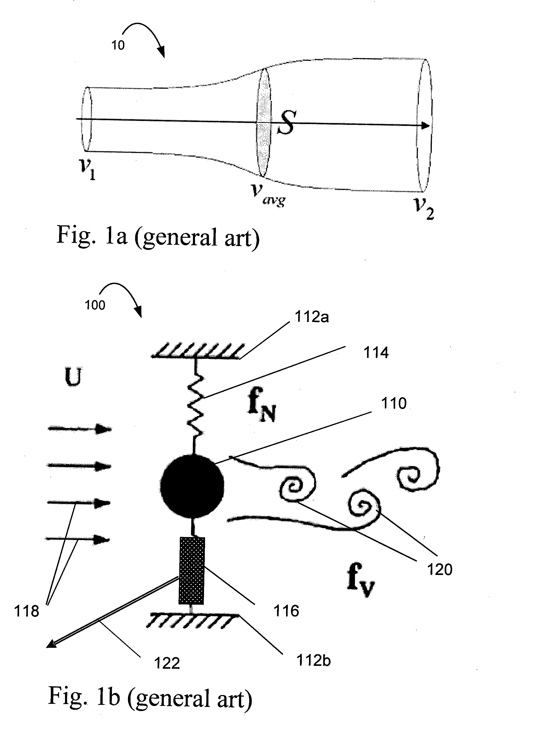
[0048]Before describing the embodiments and examples of the present invention, a theoretical analysis of vortex-induced vibrations is in place. Using the laws of conservation of mass, momentum and energy for a control volume, combined with Bernoulli's law within the control volume for a conventional horizontal axis wind turbine, the maximum possible power generation can be derived. To this end, reference is now made to the figures, FIGS. 1a-1b, which illustrate a mode of operation of vortex-induced vibration as known in the art. FIG. 1a depicts the control volume analysis. FIG. 1b illustrates a general device 100 for power generation by uncontrolled or passively controlled VIV as known in the art.

[0049]In FIG. 1a, a control volume 10 of a fluid is shown which is characterized by the upstream flow speed v1, the flow velocity v2 in the wake of a turbine, and the area S of the turbine disk. It can easily be shown that the so-called induced velocity at the disk is vavg=(v1+v2) / 2. The ma...


PUM


Abstract

A device for use in extracting energy from an incoming fluid flow is presented. The device comprises: an oscillator assembly mounted on a base, the oscillator assembly comprising: a main body for exposing to an incoming fluid flow; and a joining element attached to the main body and configured for anchoring the main body to the base and enabling oscillation of the main body with respect to the base; an operative flow affecting unit comprising at least one flow interacting element located in at least one location respectively on a surface of the main body, the operative flow affecting unit being configured and controllably operable for affecting a separation of streams of the fluid flowing over the surface of the main body; a control unit in communication with the operative flow affecting unit, the control unit being configured and operable for activating and deactivating of each of the at least one flow interacting element of the operative flow affecting unit according to a certain time pattern, the time pattern being selected such that interaction between the flow interacting element and fluid streams creates vortices in the fluid streams at a selected vortex formation frequency causing an increase in oscillation of the main body, thereby enabling conversion of motion from the oscillation into useful energy.

Description

FIELD OF THE INVENTION[0001]The present invention relates to a technique for generating useful energy from a flowing fluid, and more specifically to the use of vortex shedding to increase an oscillation of an oscillating device and converting the oscillation into energy.BACKGROUND OF THE INVENTION[0002]Ocean energy in the form of waves, currents, tides, and thermal and salinity gradients can provide an abundant supply of clean and renewable energy. Similarly, wind power may provide renewable energy. However, constructing of safe, efficient, affordable and durable system for converting fluid flow to usable energy remains challenging.[0003]When a fluid flow encounters a front surface of an object, vortices are formed behind the object. This phenomenon is called vortex shedding. The vortices are formed at a vortex formation frequency affected by such variables as the geometry of the object, the speed of the fluid flow, and the properties of the fluid. The vortex formation frequency is ...

Claims


Application Information

Patent Timeline
Patent Type & Authority Applications(United States)
IPC IPC(8): F03B17/06
CPCF03B5/00F03D5/00F05B2250/41Y02E10/28Y02E10/70F03B17/06Y02E10/20Y02E10/30
Inventor GREENBLATT, DAVID
Owner TECHNION RES & DEV FOUND LTD
Why Eureka
Try Eureka