

Linkage for guiding a flexible cable
a flexible cable and linkage technology, applied in the direction of connecting rod bearings, mechanical equipment, transportation and packaging, etc., can solve the problems of damage to structures such as hydraulic cables or electrical cables, unsatisfactory aerodynamic effects, and weakening the leading edge skin of fixed wings
- Summary
- Abstract
- Description
- Claims
- Application Information
AI Technical Summary
Benefits of technology
Problems solved by technology
Method used
Image

Examples
Embodiment Construction
)
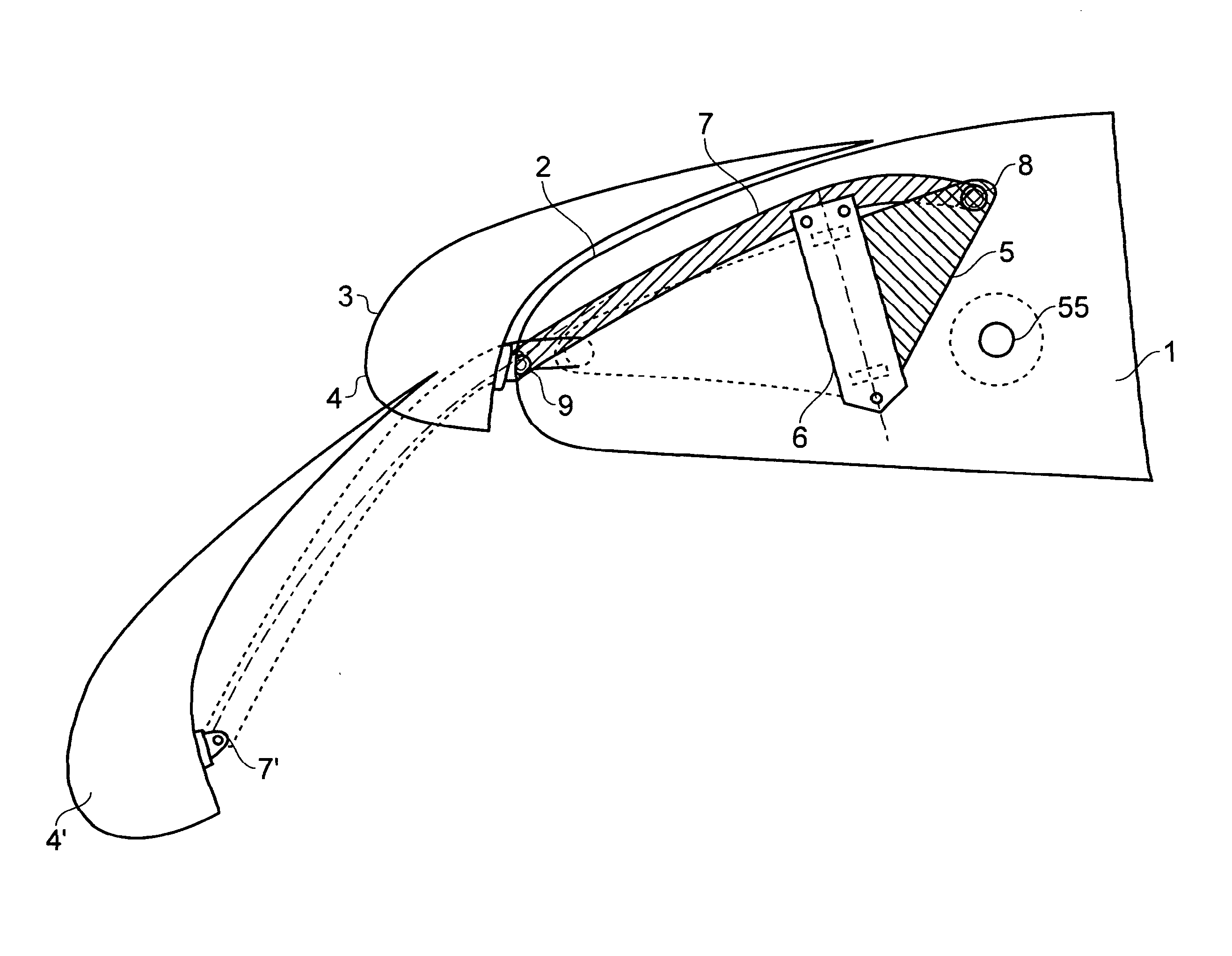
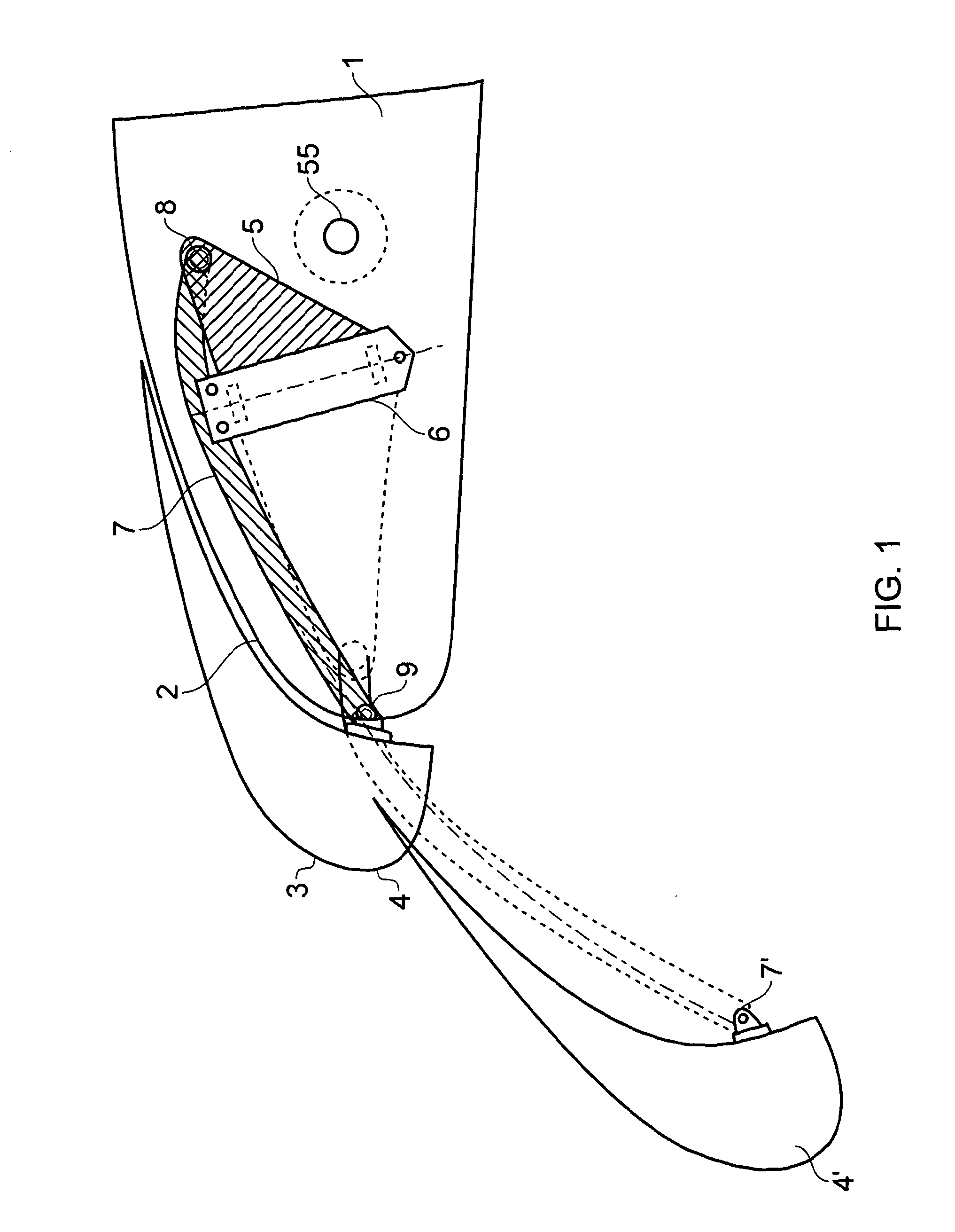
[0033]FIG. 1 is a schematic view of the leading edge of an aircraft wing, viewed in cross-section. The wing comprises a fixed wing part 1 with a D-nose fixed leading edge skin 2; and a slat 4 movable relative to the fixed wing between a retracted upper position, and an extended lowered position (labelled 4′,7′). The slat 4 is driven between its two positions by a draft shaft 55 and an actuation mechanism which is not shown. Typically the actuation mechanism comprises a slat track which extends to the rear of the slat and is driven along a curved path by a set of driven rollers.
[0034]The slat 3 carries a de-icing system (not shown) which heats the leading edge 4 of the slat 3 to prevent the build up of ice. A flexible cable (not shown in FIG. 1) extends between the fixed wing and the slat in order to carry electrical power to the de-icing system.
[0035]A linkage system guides the flexible cable and is adjustable between a retracted position (shown in solid line) when the slat is in i...
PUM
 Abstract
Description
Claims
Application Information