High extraction force ball socket

a ball socket and high extraction force technology, applied in the field of pivot joints, can solve the problems of reducing the flexibility of the tabs, not being desirable, and not being able to operate the adjuster,

Active Publication Date: 2013-09-12
BURTON TECH
View PDF13 Cites 22 Cited by
  • Summary
  • Abstract
  • Description
  • Claims
  • Application Information

AI Technical Summary

Benefits of technology

[0009]The present invention relates to an improved ball joint which includes resilient tabs that contact an inserted ball stud at a location toward the shank of the ball stud from the previously described tangent point. Certain embodiments of a ball joint in accordance with the present invention are capable of being used in automotive lamp assemblies and solve some or all of the problems raised or not solved by existing ball joints. Of course, the present invention may be used in a multitude of non-automotive lamp situations where similar performance capabilities are required.

Problems solved by technology

This configuration results in a condition where the ball stud may be pulled out of socket under certain conditions of operation, such as vibration while supporting heavier reflectors or in heavier headlamp assemblies like the one previously referenced in U.S. Pat. No. 5,360,282, leaving the adjuster non-operational.
Though pull-out of the ball stud is resisted to some degree of success, if enough pull-out force is applied, the tabs deflect and the ball stud head slips through and “pops out.” Reducing the flexibility of tabs is not a desirable option because it would either be too difficult to insert the ball stud head into socket, or the elasticity of the tabs would be lessened to the degree that they would break off during insertion of the ball stud.

Method used


Image

  • High extraction force ball socket
  • High extraction force ball socket
  • High extraction force ball socket

Examples


Embodiment Construction

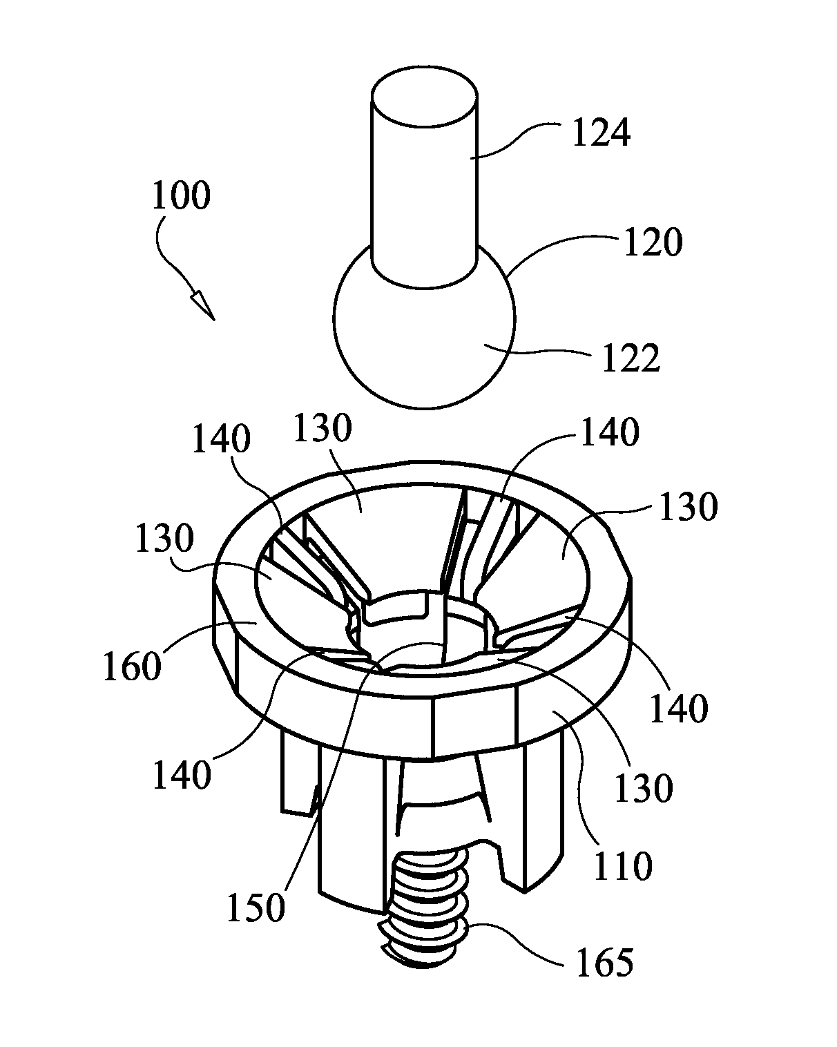
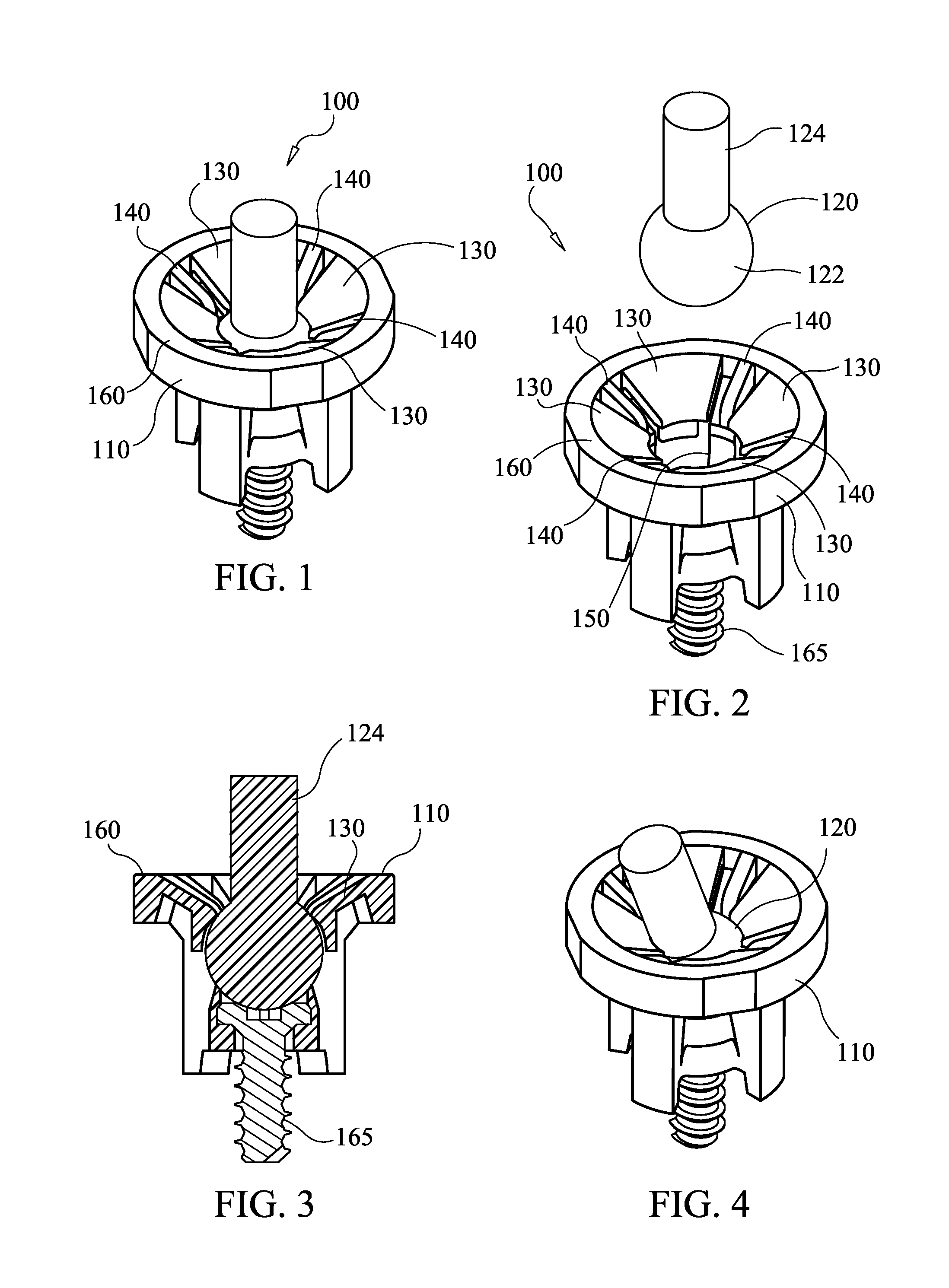
[0027]FIGS. 1-7 show one embodiment of a ball-socket 100 in accordance with the invention. The ball-socket 100 has a socket 110 and a ball stud 120. The ball stud 120 includes a spherical portion 122 and a shank 124. The socket 110 includes a plurality of resilient tabs 130 and a plurality of support legs 140. The resilient tabs 130 and support legs are attached to an exterior collar 160. Together, the resilient tabs 130 and support legs 140 combine to form a cavity 150 in which the ball stud 120 may pivot and rotate. The resilient tabs 130 elastically deform when the ball stud 120 is inserted into the socket 110. In the embodiment shown in FIGS. 1-7, the socket 110 is secured to its desired location via a screw 165.

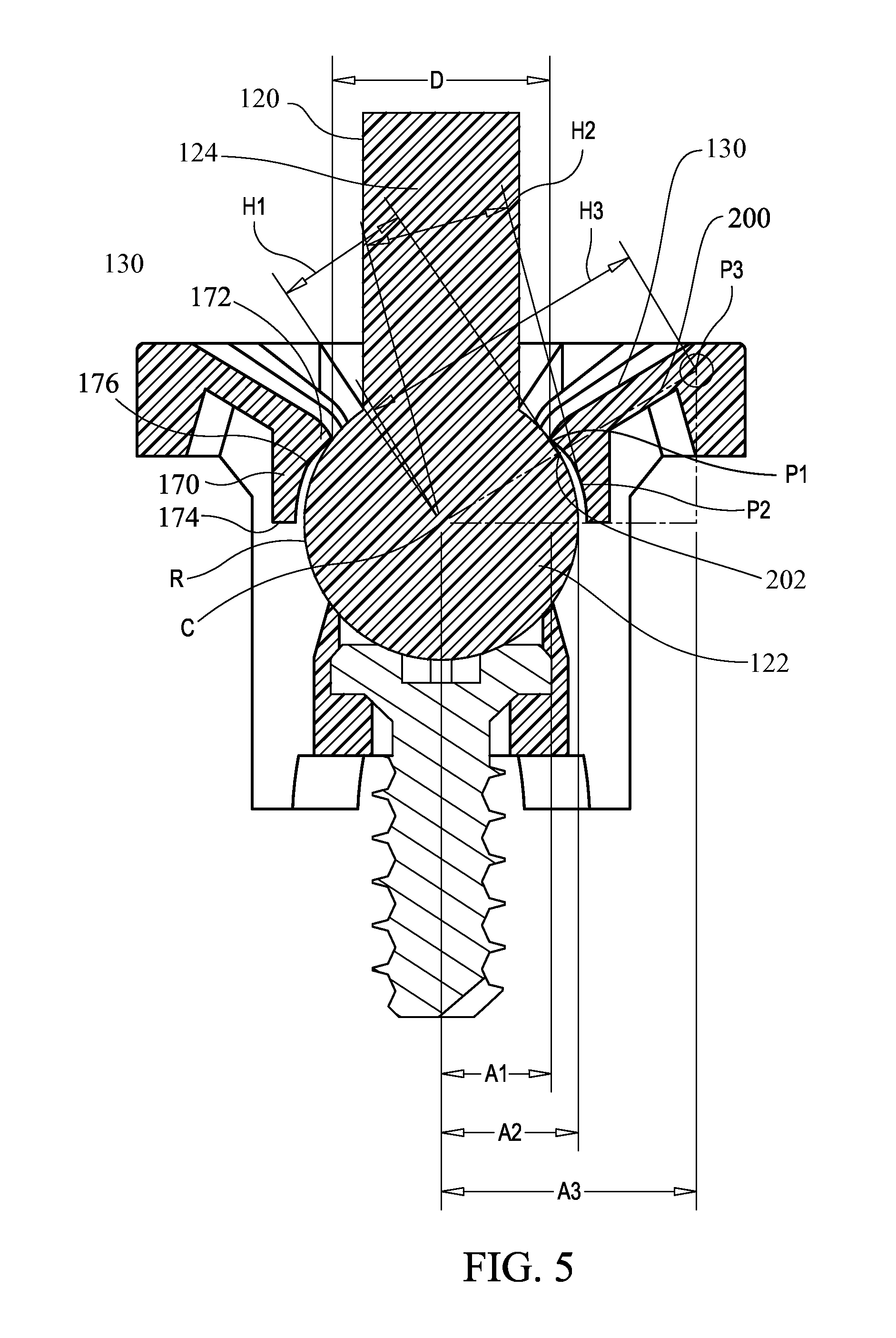
[0028]FIG. 3 shows a cross-section of the ball-socket 100. When a pull-out force is applied to the ball-stud 120, it contacts resilient tabs 130 causing a portion of the pull-out force to be transferred through the resilient tabs 130 to the exterior collar 160. In the em...


PUM

PropertyMeasurementUnit
Insertion forceaaaaaaaaaa
pull out forceaaaaaaaaaa

Abstract

A ball socket for connection with a ball stud resists accidental pull-out of the ball stud. The ball socket achieves relatively low insertion force but relatively high pull-out force resistance.

Description

CROSS-REFERENCE TO RELATED APPLICATION[0001]This application is based on and claims priority to U.S. Provisional Patent Application No. 61 / 607,117 filed on Mar. 6, 2012, the disclosure of which is incorporated herein by reference in its entirety for all purposes.FIELD OF THE INVENTION[0002]The present invention relates generally to the field of pivot joints and has been found particularly useful as a pivot joint for connecting a headlamp adjuster to a reflector inside a headlamp assembly or an external reflector and lens headlamp assembly.BACKGROUND OF THE INVENTION[0003]Pivotable spherical joints, commonly referred to as ball joints, generally include a ball stud engaged in a socket. Such joints have a wide variety of applications where a pivotable connection between two parts is desirable. For example, they may be used in many types of linear actuators and have been found to be particularly useful in automotive lamp assemblies. As seen in U.S. Pat. No. 5,707,133 the disclosure of ...

Claims


Application Information

Patent Timeline
Patent Type & Authority Applications(United States)
IPC IPC(8): F16C11/06
CPCF16C11/06F16C2226/74F16C2362/00B60Q1/068F16C11/0657Y10T403/32737F21V21/29F16C2326/01F16C2208/66B60Q2200/32F21S48/1305F16C11/069F21S41/39Y10T403/32762
Inventor BURTON, JOHN E.
Owner BURTON TECH
Why Eureka
Try Eureka