
Electrothermal Heating Device

Active Publication Date: 2013-09-12
ZOJIRUSHI CORPORATION
View PDF12 Cites 15 Cited by
  • Summary
  • Abstract
  • Description
  • Claims
  • Application Information

AI Technical Summary

Benefits of technology

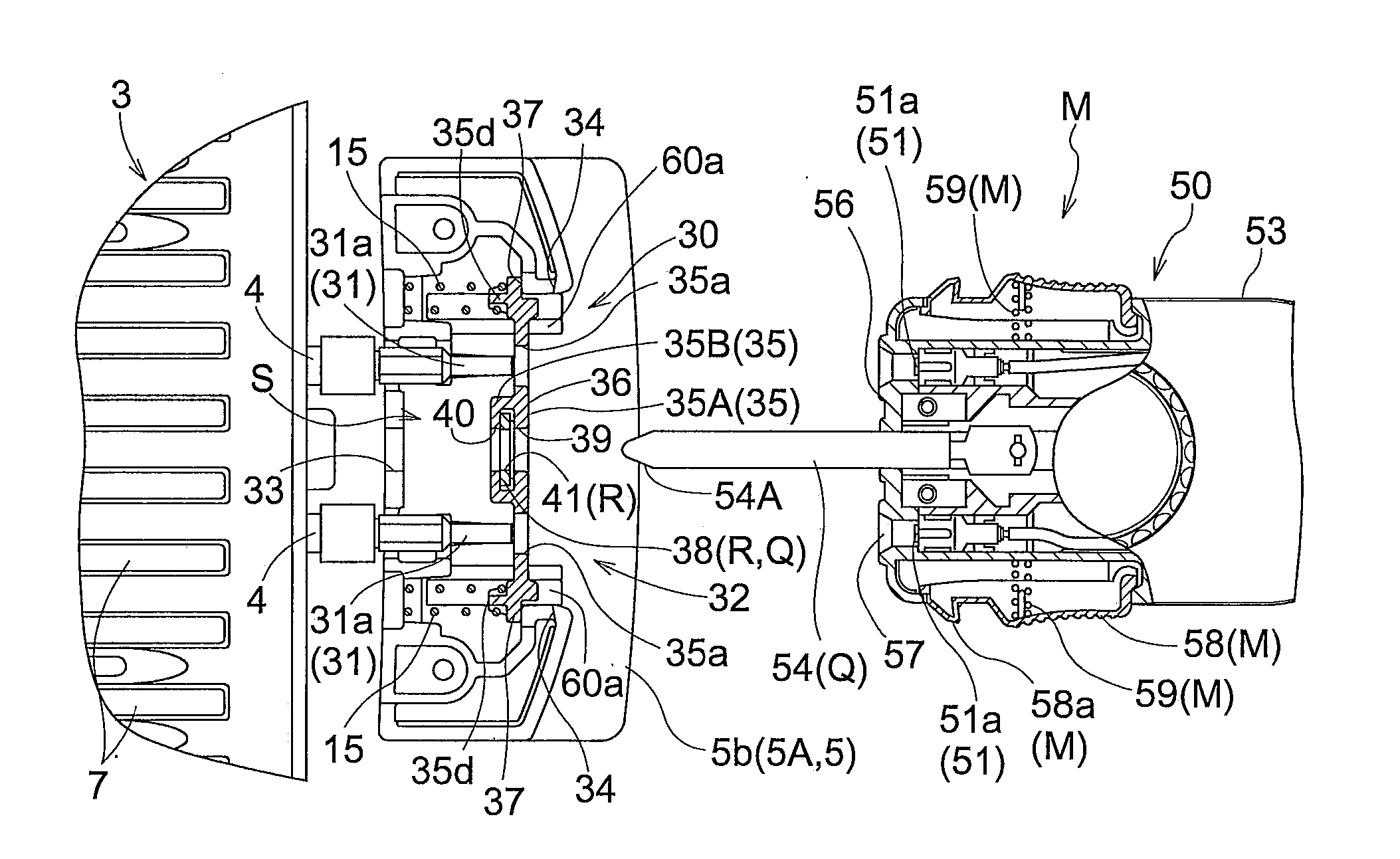
This technical effect is the creation of a protective member that closes the opening of a plug socket and creates a protected state where the socket's electroconductive part is positioned inside the interior space of the plug socket, preventing contact by a user's hand, dirt, and collisions by objects. The protective member is designed to restrict movement so that the user is prevented from approaching it, further improving safety.

Problems solved by technology

The socket-side electroconductive part electrically connected to the electrothermal heater is heated to an extremely high temperature by conducted heat from the electrothermal heater, and there is a chance of a user suffering burns or the like if the socket-side electroconductive part is accidentally touched.
In addition, if dirt or the like adheres to the socket-side electroconductive part, or if it is deformed from impact with an object, the contact resistance between the socket-side electroconductive part and the plug-side electroconductive part of the power source plug will increase, leading to the risk of heat being given off at that part.
Therefore, when, for example, a user manually presses the closing plate in the sliding direction, the tips of the electroconductive pins are exposed to the exterior of the closing plate through pin insertion holes formed in the closing plate, with the possibility of a user's hand touching the electroconductive pins, dirt adhering thereto, or an object colliding therewith.
Such a configuration raises the possibility of a user's hand touching the electroconductive pins, dirt or the like adhering thereto, or an object colliding therewith.

Method used


Image

  • Electrothermal Heating Device
  • Electrothermal Heating Device
  • Electrothermal Heating Device

Examples


Embodiment Construction

[0081]An embodiment of a heated cooking appliance will be described with reference to the drawings as an example of the electrothermal heating device according to the present invention. Examples of heated cooking appliances include hotplates, meat grills, grill pans, Japanese takoyaki makers, and the like, but the following description will feature an embodiment of a hotplate.

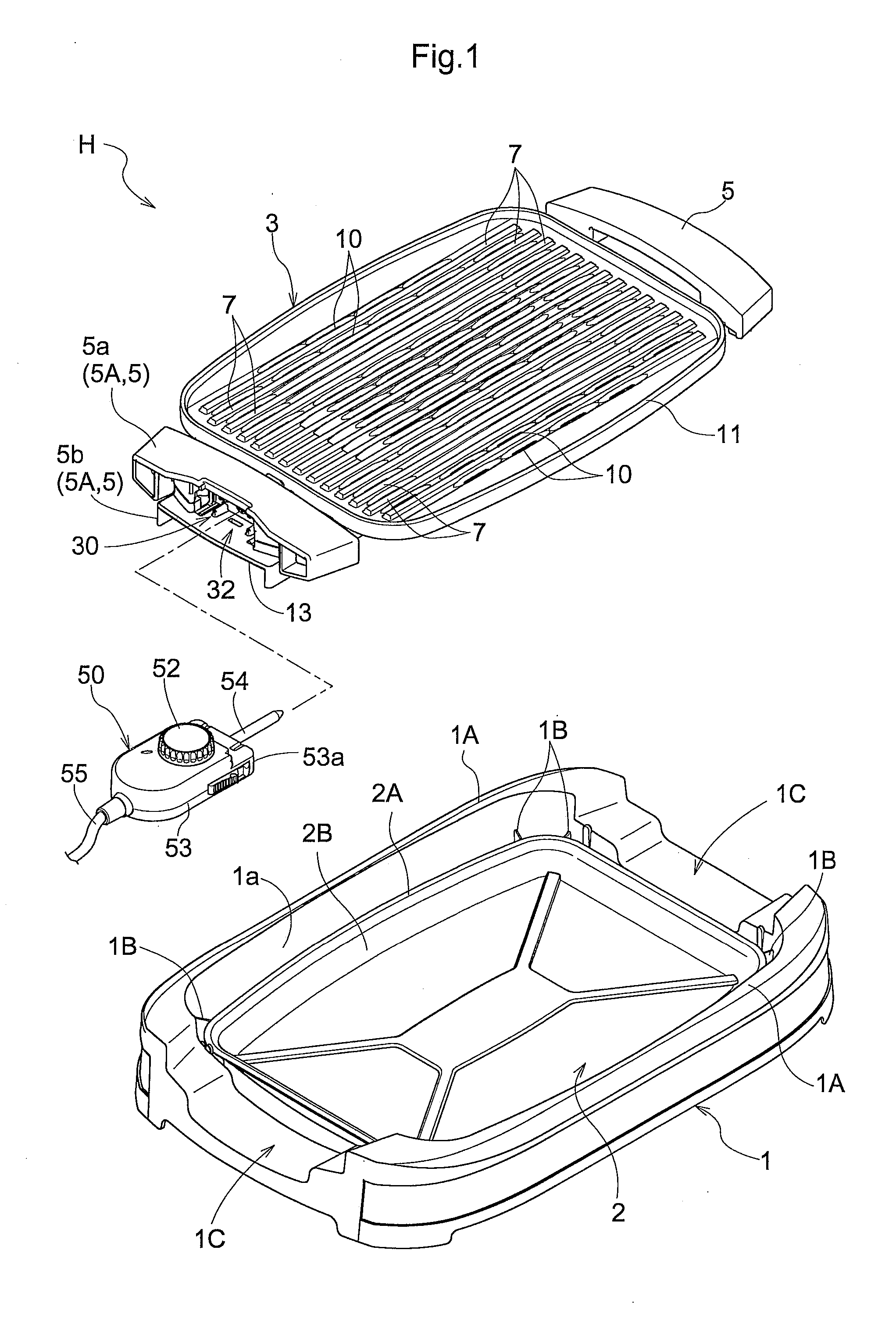
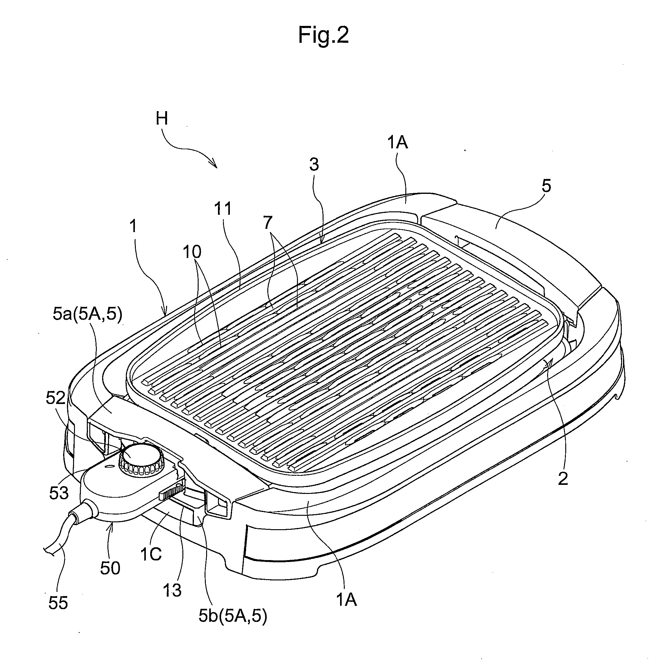
[0082]As shown in FIGS. 1-4, a hotplate H is provided with a deep dish-shaped main cooking device unit 1, a dish-shaped water dish 2 freely placeable upon and removable from the main cooking device unit 1, a plate-shaped cooking plate 3 (example of an object of heating) disposed above the dish-shaped water dish 2 and removably resting upon the main cooking device unit 1, and an electrothermal heater 4 (see FIG. 4) that receives electrical power from a power source (not shown) such as an AC power source and generates heat, heating the cooking plate 3.

[0083]As shown in FIGS. 1,2, and 5-9, the hotplate H is provid...


PUM


Abstract

An electric heating device includes a box-shaped plug socket provided with a socket-side electroconductive part electrically connected to an electric heater; a power source plug provided with a plug-side electroconductive part electrically connectable to the socket-side electroconductive part and attachable to and detachable from the plug socket; a movement-restricting mechanism for restricting the movement of a protective member both toward and away from a socket-side electroconductive part in a protected state in which the protective member closes an opening of the plug socket and the socket-side electroconductive part are positioned within an interior space; and a switching mechanism for switching the protective member from a restricted movement state into a restriction released state, in which the restriction of movement by the movement restriction mechanism is released, as the power source plug is inserted into the plug socket.

Description

BACKGROUND OF THE INVENTION[0001]1. Field of the Invention[0002]The present invention relates to an electrothermal heating device provided with a box-shaped plug socket provided with a socket-side electroconductive part electrically connected to an electrothermal heater and with an opening, and a power source plug provided with a plug-side electroconductive part electrically connectable with the socket-side electroconductive part, the plug being insertable into and removable from the plug socket via the opening.[0003]2. Description of the Related Art[0004]Examples of such electrothermal heating device include heated cooking appliances (hotplates, meat grills, grill pans, Japanese takoyaki makers, etc.), electric pots, electric kettles, humidifiers, and other electrothermal heating device provided with an electrothermal heater. Such electrothermal heating device are configured so that electrical power from a power source is supplied to the electrothermal heater via the power source p...

Claims


Application Information

Patent Timeline
IPC IPC(8): H01R13/453
CPCH01R13/4534H01R13/4538A47J37/0676H05B3/06
Inventor AONO, TADAYUKIOMBE, MASAAKIISHII, TAKUYAKAWANO, HAYATO
Owner ZOJIRUSHI CORPORATION
Learn More