Eureka AIR delivers breakthrough ideas for toughest innovation challenges, trusted by R&D personnel around the world.

Electronic control brake system for vehicles

Inactive Publication Date: 2013-09-19
MANDO CORP
View PDF6 Cites 4 Cited by
  • Summary
  • Abstract
  • Description
  • Claims
  • Application Information

AI Technical Summary

Benefits of technology

The patent text describes an electronic control brake system for vehicles that reduces the amount of friction between the brake pads and the brake discs, which can cause residual pressure.

Problems solved by technology

However, when brake pressure is greater than a road surface state or frictional force of the wheel brakes generated by the brake pressure is greater than braking force generated from tires or a road surface while the driver presses the brake pedal to allow the vehicle to be in a braking force increasing state or a braking force maintaining state, slippage of the tires on the road surface occurs.
In the conventional brake systems, a disc of the wheel brake and a pair of pads pressing both sides of the disc may minutely come into contact due to partial abrasion without generation of brake pressure during driving.
Contact between the disc and the pads generates residual frictional force and thus causes acceleration and driving loss.

Method used


Image

  • Electronic control brake system for vehicles
  • Electronic control brake system for vehicles
  • Electronic control brake system for vehicles

Examples


Embodiment Construction

[0019]Reference will now be made in detail to the embodiments of the present invention, examples of which are illustrated in the accompanying drawings, wherein like reference numerals refer to like elements throughout.

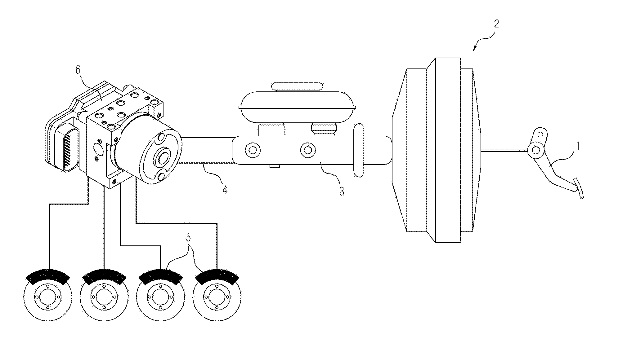
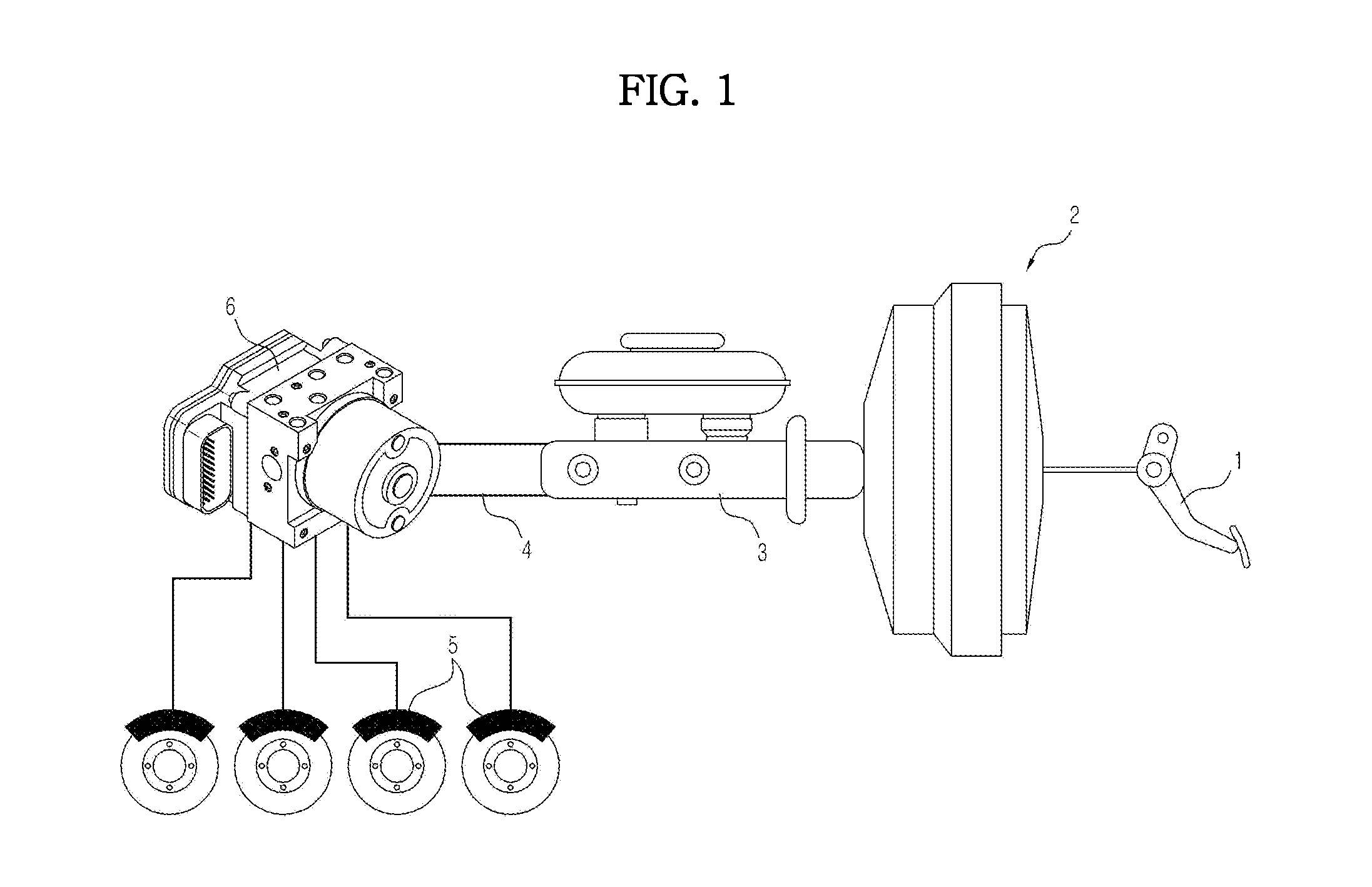
[0020]FIG. 1 is a view schematically illustrating an electronic control brake system for vehicles in accordance with one embodiment of the present invention. With reference to FIG. 1, the electronic control brake system for vehicles includes a brake pedal 1, a booster 2 amplifying foot effort on the brake pedal 1 and outputting the amplified foot effort, a master cylinder 3 converting pressure amplified by the booster 2 into hydraulic pressure, and a modulator block 6 connected to the master cylinder 3 by a hydraulic pipe 4 and controlling transmission of brake hydraulic pressure to respective wheel brakes 5. Although not illustrated in detail, the wheel brake 5 includes a caliper device including a disc installed on a wheel, pads located at both sides of the disc, and...


PUM


Abstract

Disclosed is an electronic control brake system for vehicles which suppresses residual frictional force generated due to contact between pads and a disc, the electronic control brake system including an electronic control unit enabling a control of an anti-lock brake system (ABS) mode and a traction control system (TCS) mode, a master cylinder forming brake hydraulic pressure according to operation of a brake pedal, wheel brakes, each of which includes a caliper device including a disc provided in a vehicle and advancing and retracting a pair of pads pressing the disc so as to exhibit wheel braking force by the brake hydraulic pressure transmitted from the master cylinder, plural NO type solenoid valves and NC type solenoid valves respectively provided at upstream sides and downstream sides of the wheel brakes and controlling the flow of the brake hydraulic pressure, low pressure accumulators in which a fluid discharged from the wheel brakes is temporarily stored during the ABS mode braking of the solenoid valves, pumps and a motor pressurizing the fluid stored in the low pressure accumulators so as to discharge the fluid to the wheel brakes or the master cylinder, an NC type shuttle valve provided on an oil suction path connecting from the master cylinder to an inlet of the pump so as to perform the TCS mode, a TC solenoid valve provided between an outlet of the pump and the master cylinder, and a hydraulic control device provided between the outlet of the pump 13 and the TC solenoid valve, wherein the electronic control unit moves a part of a fluid in a closed circuit section L2 provided at a wheel brake side toward the hydraulic control device provided at an outlet side of the pump by operating the pump, thereby reducing the fluid volume and thus effectively preventing the residual fictional force generated due to contact between the disc and the pads.

Description

CROSS-REFERENCE TO RELATED APPLICATION[0001]This application claims the benefit of Korean Patent Application No. 2012-0023702, filed on Mar. 8, 2012 in the Korean Intellectual Property Office, the disclosure of which is incorporated herein by reference.BACKGROUND[0002]1. Field[0003]Embodiments of the present invention relate to an electronic control brake system for vehicles, and more particularly, to an electronic control brake system for vehicles which prevents residual frictional force generated between a disc and pads.[0004]2. Description of the Related Art[0005]In general, a vehicle is provided with a plurality of wheel brakes, each of which includes a caliper device including a disc and a pair of pads to brake a front wheel or a rear wheel to decelerate or stop the vehicle, a booster forming brake hydraulic pressure and transmitting the brake hydraulic pressure to the wheel brakes and a master cylinder, and thus, when a driver presses a brake pedal, the hydraulic pressure form...

Claims


Application Information

Patent Timeline
IPC IPC(8): B60T13/14B60T13/68B60T1/06
CPCB60T13/147B60T8/4872B60T13/686B60T1/065B60T8/36B60T13/10
Inventor KIM, HEE JUN
Owner MANDO CORP
Why Eureka
Eureka Blog
Learn More