Fixture with Voided Surface Features to Maximize Drying of Fabric Articles
- Summary
- Abstract
- Description
- Claims
- Application Information
AI Technical Summary
Benefits of technology
Problems solved by technology
Method used
Image
Examples
first embodiment
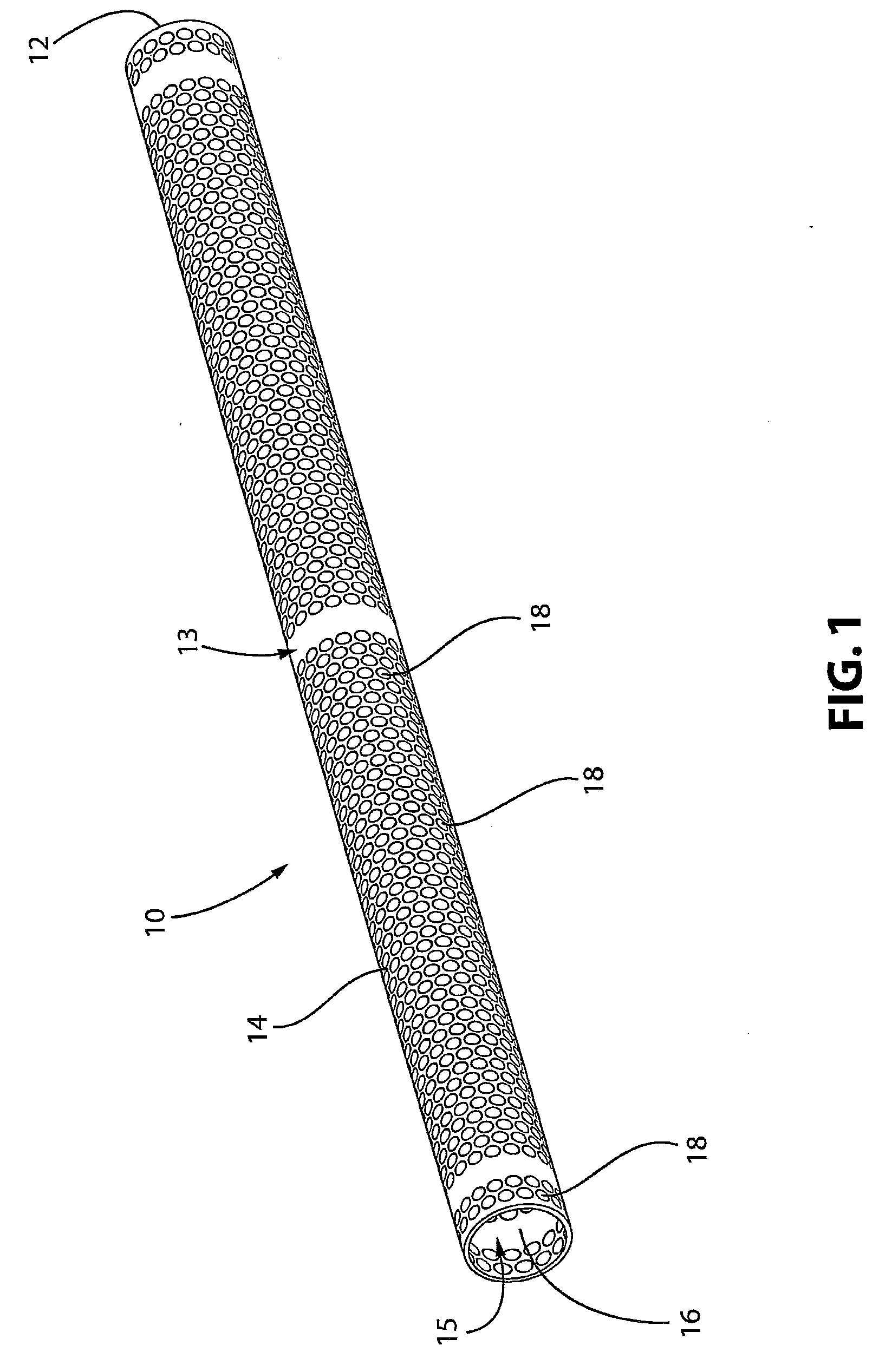
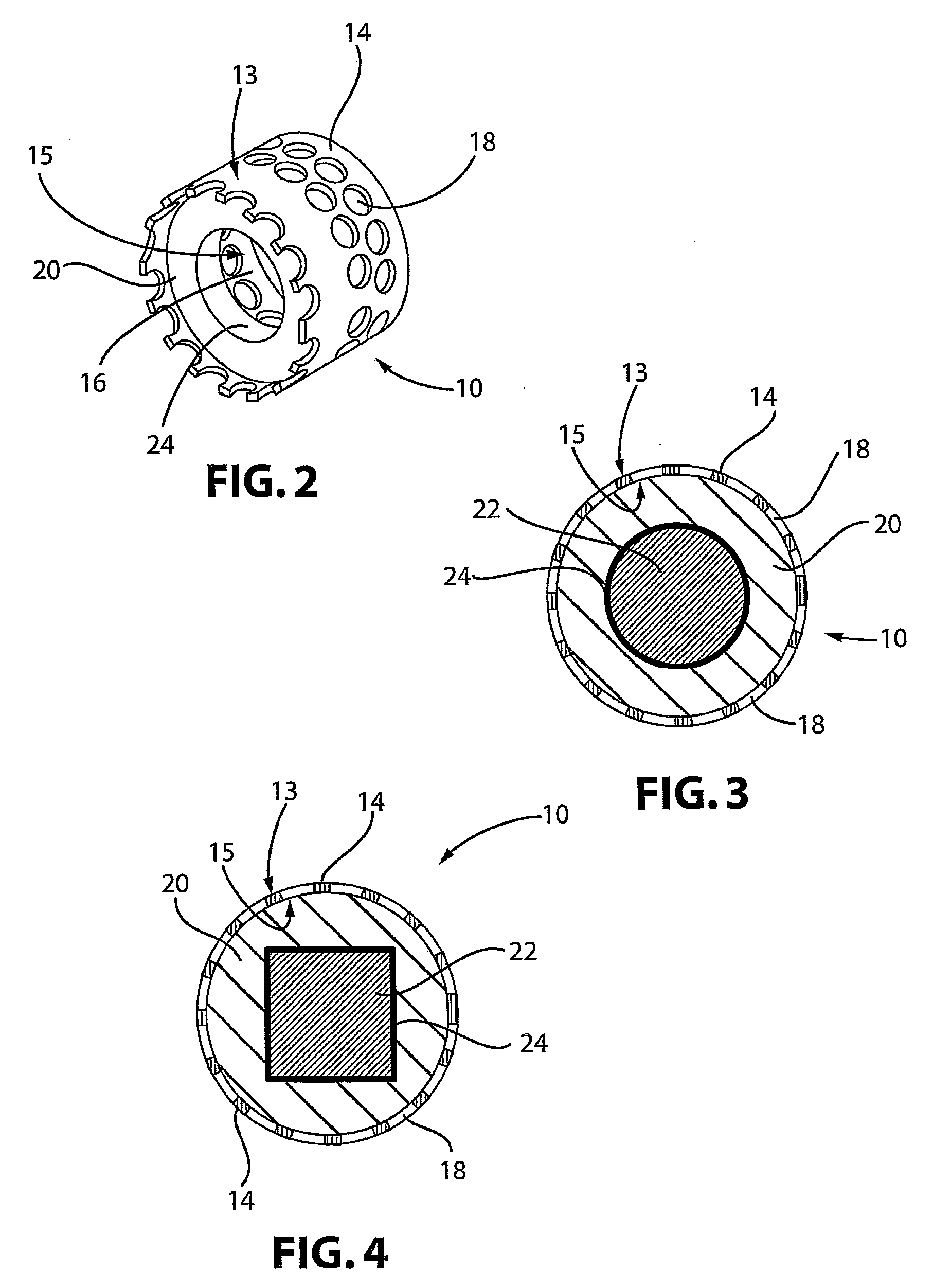
[0036]FIGS. 1-3 illustrate a fabric drying fixture 10 for hanging fabric articles including, but not limited to, towels and washing cloths. FIGS. 1 and 2 show the fixture 10 prior to installation on a rod 22. FIG. 3 shows the fixture 10 as installed on a rod 22. The fixture 10 is adapted for use with an existing rod 22 provided for hanging fabric articles.
[0037]Fixture 10 comprises an elongated body 12 with an outer surface 13 and an inner surface 15. The inner surface 15 defines at least one sidewall 14 that defines a central passageway 16. In the embodiment shown in FIGS. 1-3, the elongated body 12 has a cylindrical shape provided by a single sidewall 14 and has a circular cross-section. However, as can be envisioned by a person skilled in the art, the cross-section of the elongated body 12 can take any suitable shape including, but not limited to, an oval, a square, a rectangle, a triangle, and a polygon. Of course, the later four shapes will have more than one sidewall 14.
[0038]...
second embodiment
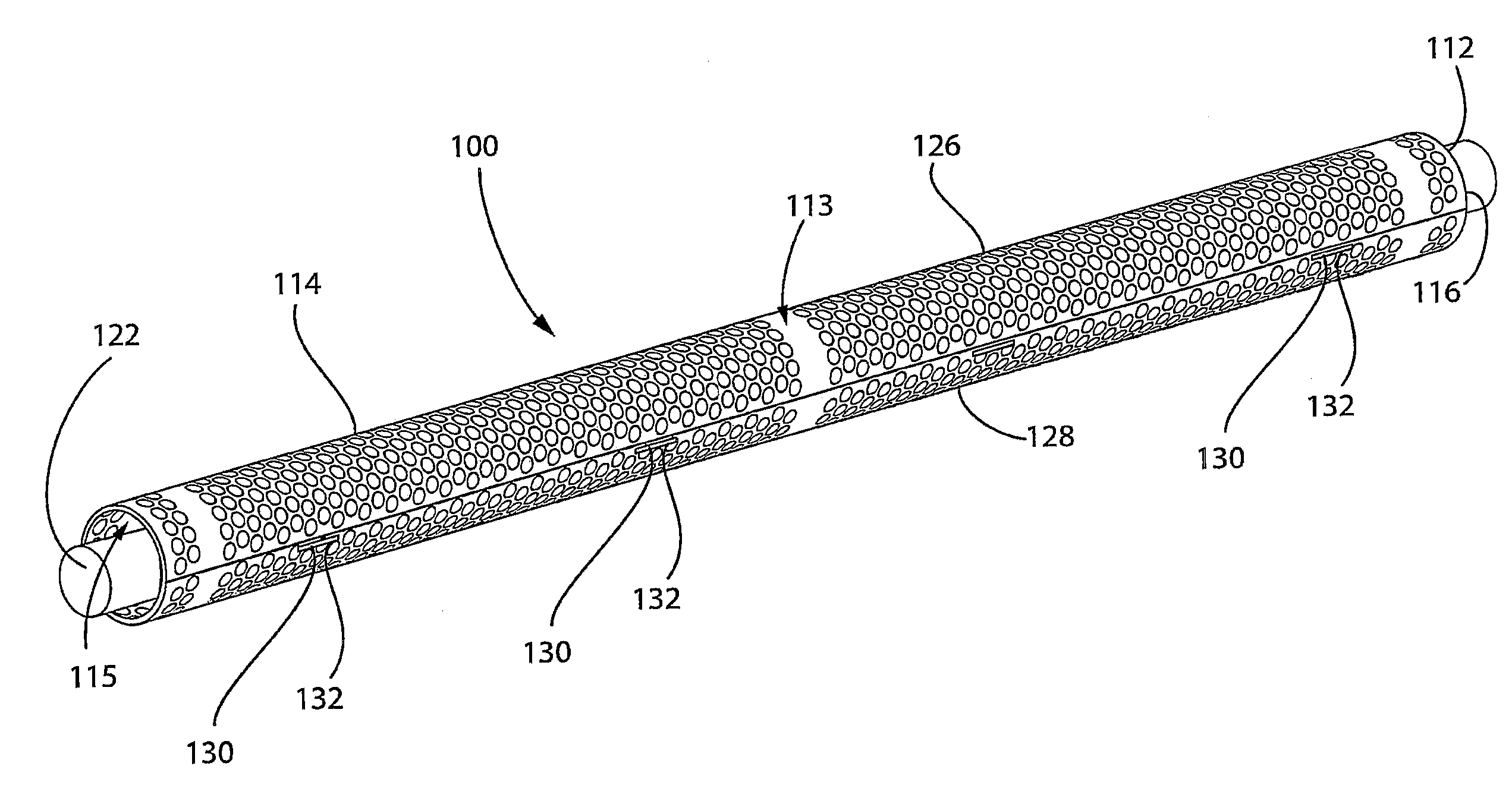
[0042]the inventive fixture 100 is shown in FIGS. 5-8. FIGS. 5 and 6 show the fixture 100 prior to installation on a rod 122. FIGS. 7 and 8 show the fixture 100 as installed on a rod 122.
[0043]The fixture 100 comprises an elongated body 112 with an outer surface 113 and an inner surface 115. The inner surface 115 defines at least one sidewall 114 that defines a central passageway 116. In the embodiment shown in FIGS. 5-8, the elongated body 112 has a cylindrical shape provided by a single sidewall 114 and has a circular cross-section. However, as can be envisioned by a person skilled in the art, the cross-section of the elongated body 112 can take any suitable shape including, but not limited to, an oval, a square, a rectangle, a triangle, and a polygon. Of course, the later four shapes will have more than one sidewall 114.
[0044]The elongated body 112 has at least two portions 126, 128 that are connected to form the sidewall 114. As can be envisioned by a person skilled in the art, ...
embodiment 10
[0045]The elongated body 112 has a plurality of openings 118 therethrough extending from the outer surface 113 to the inner surface 115 of the elongated body 112 as described above with respect to the first described embodiment 10.
[0046]At least one spacer 120 is disposed in the central passageway 116 of the elongated body 112. The spacer 120 may be configured as described above with respect to the first described embodiment 10. Alternatively, as shown in the embodiment ofFIGS. 5-8, the spacer 120 may comprise at least two portions 134, 136. Preferably, each portion 134, 136 of the spacer 120 corresponds to a portion 126, 128 of the elongated body 112 such that when the portions 126, 128 of the elongated body 112 are connected to form the sidewall 114, corresponding portions 134, 136 of the spacer 120 are adjacent to one another to provide the spacing of the rod 122 from the sidewall 114. In the embodiment shown in FIGS. 5-8, the portions 134, 136 of the spacer 120 are in the shape ...
PUM
 Abstract
Description
Claims
Application Information
 - R&D
- Intellectual Property
- Life Sciences
- Materials
- Tech Scout
- Unparalleled Data Quality
- Higher Quality Content
- 60% Fewer Hallucinations
Browse by: Latest US Patents, China's latest patents, Technical Efficacy Thesaurus, Application Domain, Technology Topic, Popular Technical Reports.
© 2025 PatSnap. All rights reserved.Legal|Privacy policy|Modern Slavery Act Transparency Statement|Sitemap|About US| Contact US: help@patsnap.com


