
Enhanced Auto-Monitoring Circuit and Method for an Electrical Device

a technology of automatic monitoring and circuit, applied in the direction of coupling device connection, protective switch operating/release mechanism, emergency protective arrangement for limiting excess voltage/current, etc., can solve the problem of occupying a substantial amount of physical space, wasting available space, and limited in siz

Active Publication Date: 2013-09-19
HUBBELL INC
View PDF4 Cites 48 Cited by
  • Summary
  • Abstract
  • Description
  • Claims
  • Application Information

AI Technical Summary

Benefits of technology

The invention described in this patent addresses issues with conventional circuit interrupting devices by employing a space-efficient configuration and industry compliant means to prevent miswiring. It also includes an auto-monitoring circuit to determine if the device is operating properly. The invention provides a method for operating and testing a ground fault circuit interrupter by periodically running an auto-monitoring routine and measuring the detection of a test current. The invention also includes a circuit interrupting device with a hot conductive line terminal and a neutral conductive line terminal for carrying current, a detection means for detecting a net current passing through a transformer, and an auto-monitoring means for generating the test net current and determining if the detection means is successfully detecting the test net current.

Problems solved by technology

Such protection circuitry and the associated mechanisms normally take up a substantial amount of the physical space within a receptacle housing, the size of which is limited by the standard junction boxes in which they must fit.
Despite the trend toward miniaturization, such arrangements tend to be wasteful of available space.
Conventional devices that may or may not address one or more of these additional industry requirements tend to be too large, ineffective, and / or do not provide a robust method for confirming proper functioning of the device.

Method used


Image

  • Enhanced Auto-Monitoring Circuit and Method for an Electrical Device
  • Enhanced Auto-Monitoring Circuit and Method for an Electrical Device
  • Enhanced Auto-Monitoring Circuit and Method for an Electrical Device

Examples


Embodiment Construction

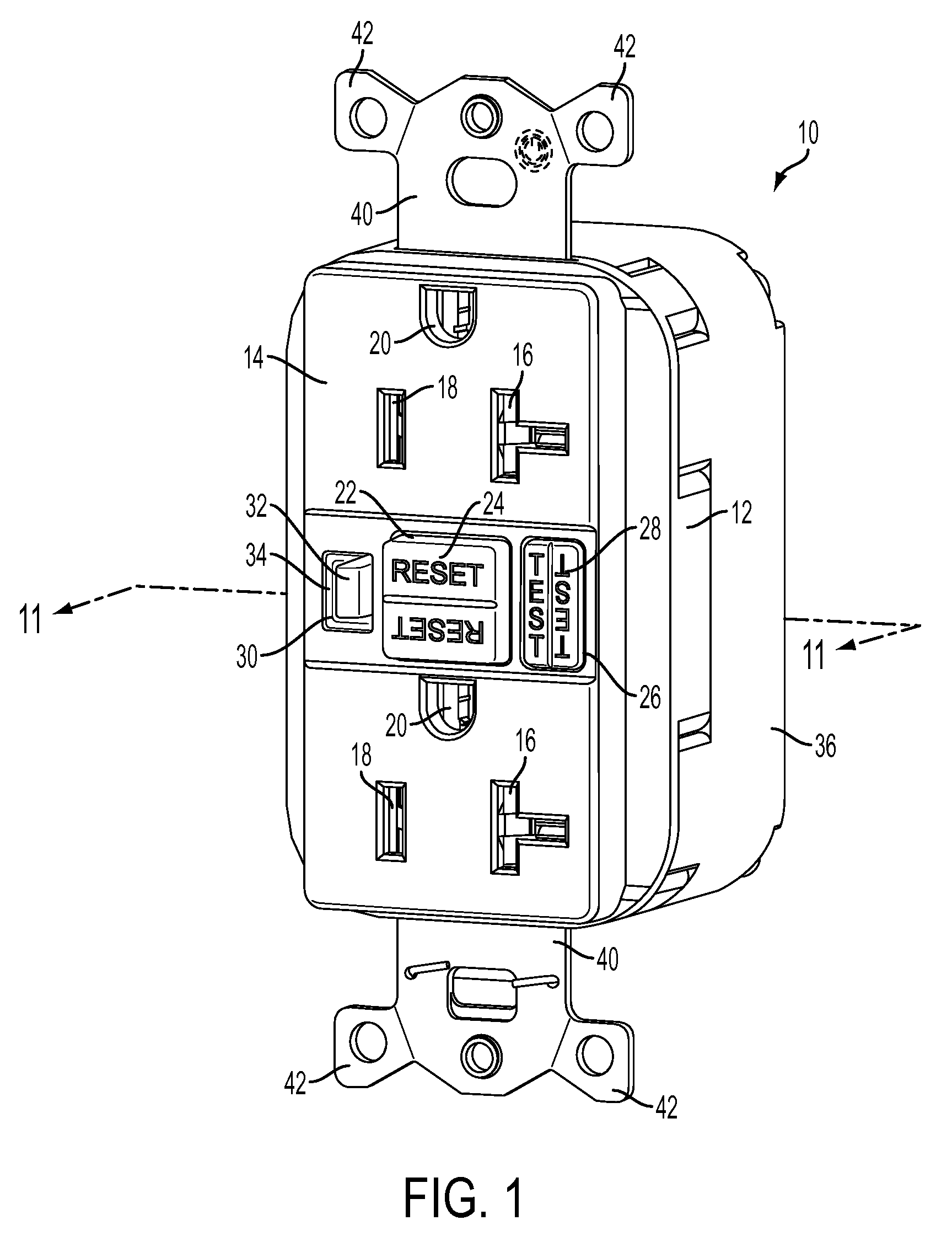
[0038]As described herein, terms such as “front,”“rear,”“side,”“top,”“bottom,”“above,”“below,”“upwardly” and “downwardly” are intended to facilitate the description of the electrical receptacle of the invention, and are not intended to limit the structure of the invention to any particular position or orientation.

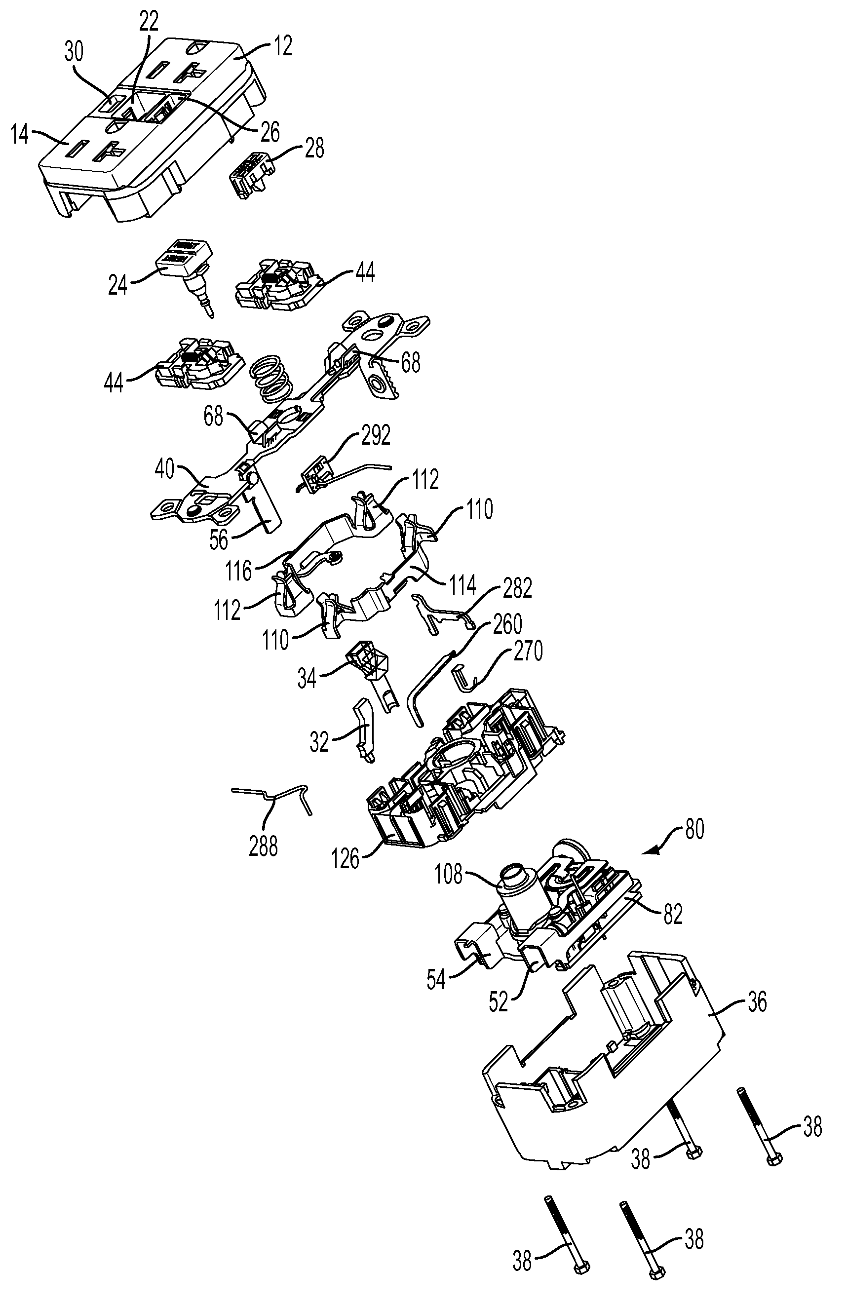
[0039]Exemplary embodiments of devices consistent with the present invention include one or more of the novel mechanical and / or electrical features described in detail below. Such features include a compact latching mechanism that efficiently utilizes the space within the device housing to provide additional area for additional features and / or components. For example, certain types of GFCI devices accommodate a separate plug on the back side of the device for connecting AC power to the device (e.g., SNAPConnect® devices by Hubbell Incorporated). To accommodate the additional plug it is beneficial to reconfigure certain components within the device housing, such as the latch...


PUM


Abstract

A resettable switching apparatus, useful in a GFCI receptacle, has an auto-monitoring circuit for automatically testing various functions and structures of the device. The auto-monitoring circuit initiates an auto-monitoring routine which, among other things, establishes a test fault situation on either the positive or negative half-wave of the power cycle and determines whether the detection mechanisms within the device appropriately detect the test fault and whether the device would trip in the event of an actual fault. Additional functionality of the auto-monitoring circuit permits automatic verification that the device is properly wired, that is, not miswired, and determines whether the device has reached the end of its useful life.

Description

CROSS-REFERENCE TO RELATED APPLICATIONS[0001]This application contains subject matter related to subject matter contained in copending U.S. Patent Applications filed on even date herewith, application numbers not assigned yet, entitled, “SOLENOID COIL HAVING AN ENHANCED MAGNETIC FIELD,” by Stephen P. Simonin, “COMPACT LATCHING MECHANISM FOR SWITCHED ELECTRICAL DEVICE,” by Gaetano Bonasia and Kenny Padro and “REINSTALLABLE CIRCUIT INTERRUPTING DEVICE WITH VIBRATION RESISTANT MISWIRE PROTECTION,” by Gaetano Bonasia et al., which applications are assigned to the assignee hereof, and the entire contents of each of which are expressly incorporated herein by reference.BACKGROUND OF THE INVENTION[0002]1. Field of the Invention[0003]The present application relates generally to switched electrical devices. More particularly, the present application is directed to circuit interrupting devices, such as ground fault circuit interrupter (GFCI) devices, that switch to a “tripped” or unlatched sta...

Claims


Application Information

Patent Timeline
Patent Type & Authority Applications(United States)
IPC IPC(8): H02H3/08
CPCH02H3/33H01R13/66H01H83/04H01H71/58H01R13/6616H01R13/6625H01R13/6633H01R13/6666H01R13/68H02H3/08
Inventor BONASIA, GAETANOPADRO, KENNY
Owner HUBBELL INC
Learn More