
Superheat Sensor

Active Publication Date: 2013-09-19
ZHEJIANG DUNAN HETIAN METAL CO LTD
View PDF26 Cites 22 Cited by
  • Summary
  • Abstract
  • Description
  • Claims
  • Application Information

AI Technical Summary

Benefits of technology

The present patent describes different embodiments of a superheat sensor. The sensor includes a housing, a pressure sensor, a fluid passageway, and a processor. The sensor can be connected to different fluid systems and can sense the temperature of the fluid as it flows through the system. The sensor can also detect the type of fluid and calculate the superheat of the fluid. The sensor can be calibrated and can store superheat and related data. The technical effects of this patent are the development of a versatile and efficient superheat sensor that can be easily connected to different fluid systems without the need for re-calibration.

Problems solved by technology

Typical superheat sensors do not provide automatic fluid-type detection, high sensitivity, and resolution under a wide range of pressures, store superheat and related parametric history, generate alarms, and provide a variety of industry standard reporting options.

Method used


Image

  • Superheat Sensor
  • Superheat Sensor
  • Superheat Sensor

Examples


first embodiment

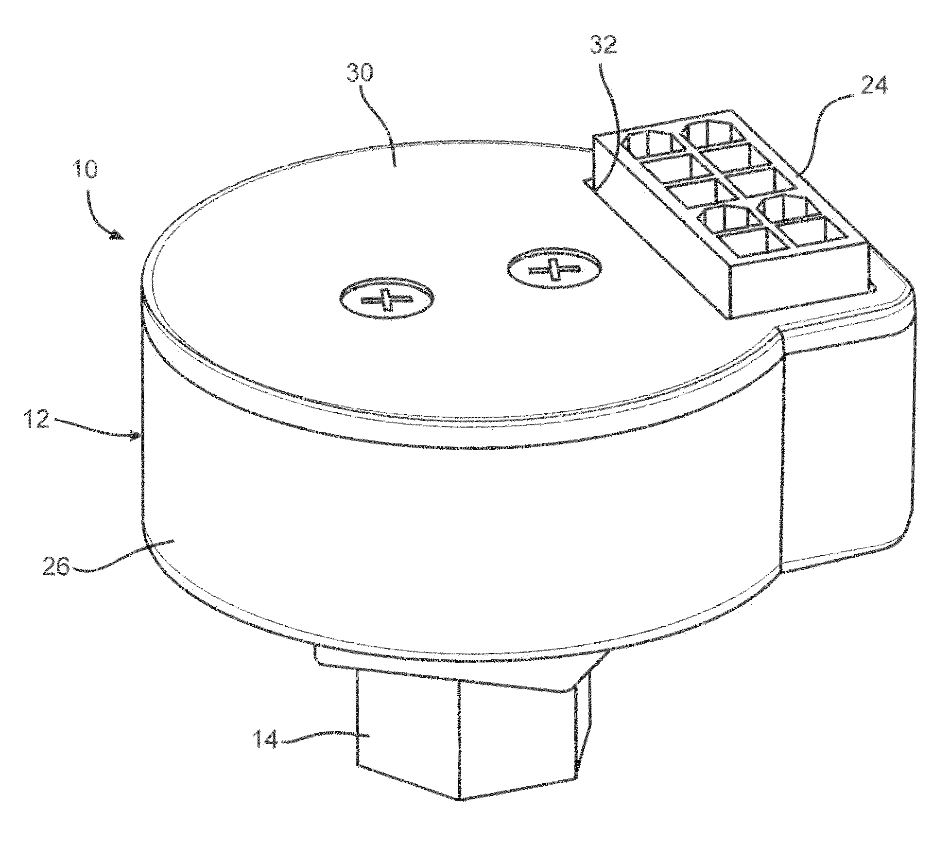
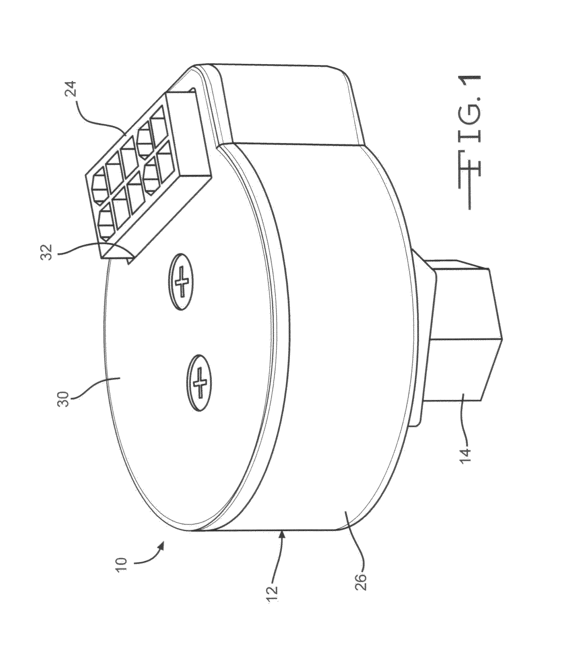
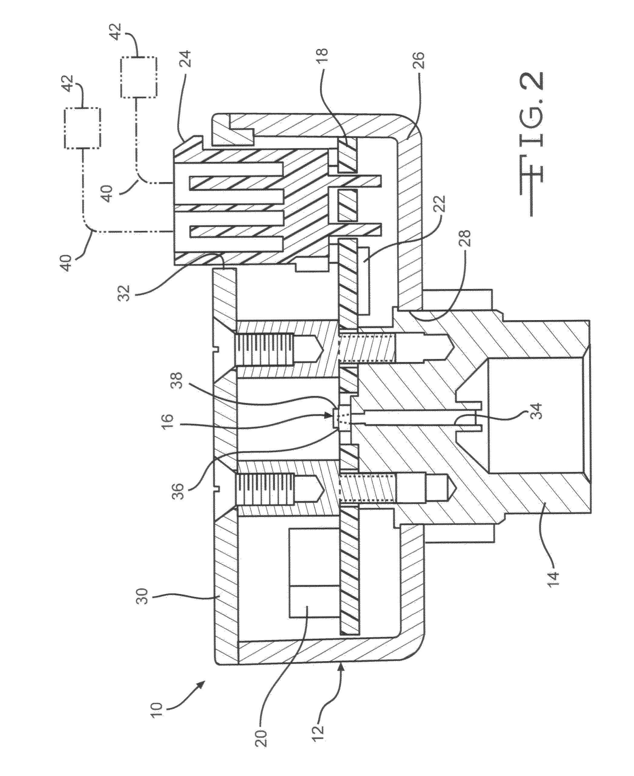
[0025]Referring now to FIGS. 1 and 2, the universal superheat sensor 10 includes a housing 12, a fluid inlet member 14, an integrated pressure and temperature sensor 16, a printed circuit board (PCB) 18, a superheat processor 20, a data-reporting or communication module 22, and an Input / Output (IO) module 24. It will be understood that in lieu of the PCB 18, alternative substrates may be used for mounting electronic components. For example, electronic components, including but not limited to those disclosed below, may be mounted on a substrate formed from a polymer, ceramic, metal, or other desired material.

[0026]The housing 12 is the enclosure for all or a portion of the components of the universal superheat sensor 10. The illustrated housing 12 is provides a hermetic or airtight sealed space within which the measurement of the fluid may occur. The illustrated housing 12 includes a body 26 having an opening 28 in which the fluid inlet member 14 is mounted, and a cover 30 having an ...

second embodiment

[0037]Referring again to FIG. 3, the universal superheat sensor is shown at 60. The illustrated universal superheat sensor 60 includes the housing 12, the fluid inlet member 14, the PCB 18, the superheat processor (not shown in FIG. 3), the communication module (not shown in FIG. 3), the IO module 24, an internal pressure sensor 62, and an external temperature sensor 44, as described above. As described above, any desired number of external temperature sensors 44 may be connected to the IO module 24 to simultaneously measure the temperature at multiple components or devices.

third embodiment

[0038]Referring now to FIG. 4, the universal superheat sensor is shown at 70. The illustrated universal superheat sensor 70 includes the housing 12, the fluid inlet member 14, the PCB 18, the superheat processor (not shown in FIG. 4), the communication module (not shown in FIG. 4), the IO module 24, an internal pressure sensor 62, and an internal temperature sensor 72. It will be understood the any desired number of external temperature sensors 44 may also be connected to the IO module 24 to simultaneously measure the temperature internally and at multiple components or devices. In addition to one or more external temperature sensors 44, if desired, the universal superheat sensor 80 may also include one or more of the target devices 42 that may be connected to the IO module 24 of the universal superheat sensor 80 via the backbone 40, as described above.


PUM


Abstract

A superheat sensor includes a housing, a pressure sensor mounted within the housing, a temperature sensor that is integrated to the pressure sensor, and / or is external to the pressure sensor, a fluid passageway connecting the pressure sensor to a source of superheat fluid, and a processor.

Description

CROSS REFERENCE TO RELATED APPLICATIONS[0001]This application claims the benefit of U.S. Provisional Application No. 61 / 611,747 filed Mar. 16, 2012.BACKGROUND[0002]Various embodiments of a fluid sensor are described herein. In particular, the embodiments described herein relate to an improved superheat sensor.[0003]There are many fluid system applications that require knowledge of a fluid's superheat in order to optimize the state of the fluid system. These systems include, but are not limited to, HVAC systems. Fluids that may be used within these systems include, but are not limited to, refrigerants.[0004]As used herein, the term superheat is defined as the condition where the fluid, regardless of the system type, has excess energy relative to the fluid's boiling point. This excess energy may be measured as the number of degrees of temperature above the fluid's boiling point, or superheat.[0005]Methods of measuring superheat are known. For example, U.S. Pat. No. 5,070,706 discloses...

Claims


Application Information

Patent Timeline
IPC IPC(8): G01K13/02G01L7/00G01K1/00
CPCG01K13/02G01K2201/00G01K13/026G01K15/005
Inventor ARUNASALAM, PARTHIBANLONG, WAYNE C.
Owner ZHEJIANG DUNAN HETIAN METAL CO LTD
Learn More