
Surface texture measurement device

Active Publication Date: 2013-09-19
MITUTOYO CORP
View PDF7 Cites 4 Cited by
  • Summary
  • Abstract
  • Description
  • Claims
  • Application Information

AI Technical Summary

Benefits of technology

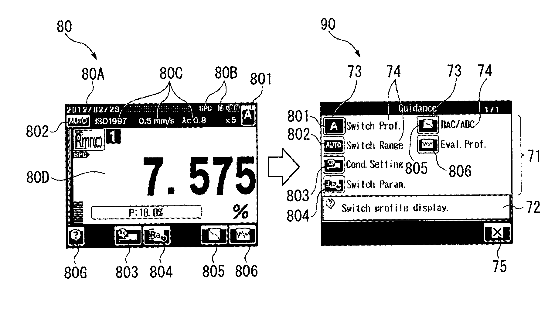
The present invention is a portable surface texture measurement device with a small display screen. The invention aims to efficiently display necessary and sufficient guidance items on the device. The device includes an operation portion and a controller that displays an operation screen and a guidance screen based on the operation of the operation portion. The operation screen displays icons for buttons and their functions, while the guidance screen displays an icon list with the functions of the buttons. This allows the user to easily identify the functions of the buttons without having to switch screens. The guidance screen can be displayed in a single page format when the number of buttons is equal to or less than a maximum button number, or in a multiple page format when the number exceeds the maximum button number. The invention provides efficient guidance in a small device with a small screen and a limited number of buttons.

Problems solved by technology

For instance, in the surface texture measurement device, due to the small size, a display size in a main body is restricted and an amount of information displayable at once is thus limited.
However, since such a surface texture measurement device has multiple functions, a wide variety of content is displayed, which results in a great number of similar abbreviated words and icons.
Accordingly, even an experienced user may have difficulty in identifying the abbreviated words and icons, and an inexperienced user or a user who seldom operates the device may not be able to understand the abbreviated words or icons.
For the case of the small surface texture measurement device that is carried to a measurement site, however, even a simple field manual may be difficult for the user to carry together with the device or to refer to during a measurement, resulting in lowered work efficiency.
However, the technologies of Related Arts 2 to 4 are each applied to a stationary device that has ample space in a display screen, and cannot be fully accommodated in a small display screen in a small device such as in Related Art 1. For example, although a help button is provided for each function in Related Art 2, there is not enough space in the small display screen to accommodate a large number of buttons having similar functions.
Accordingly, one operation is not enough to lead to the desired guidance, and thus the technology is difficult to employ from a viewpoint of work efficiency.

Method used


Image

  • Surface texture measurement device
  • Surface texture measurement device
  • Surface texture measurement device

Examples


Embodiment Construction

[0038]The particulars shown herein are by way of example and for purposes of illustrative discussion of the embodiments of the present invention only and are presented in the cause of providing what is believed to be the most useful and readily understood description of the principles and conceptual aspects of the present invention. In this regard, no attempt is made to show structural details of the present invention in more detail than is necessary for the fundamental understanding of the present invention, the description is taken with the drawings making apparent to those skilled in the art how the forms of the present invention may be embodied in practice.

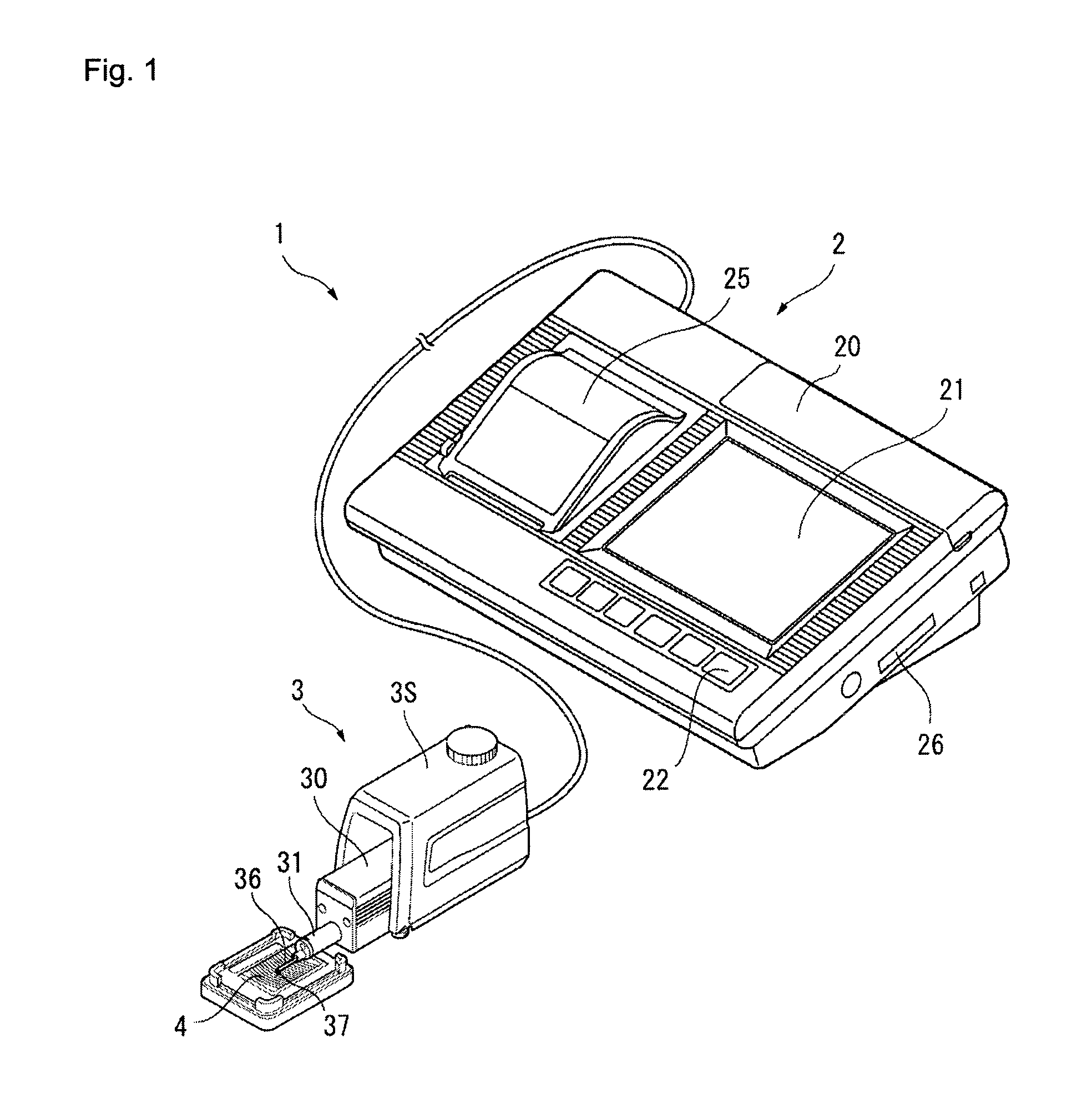
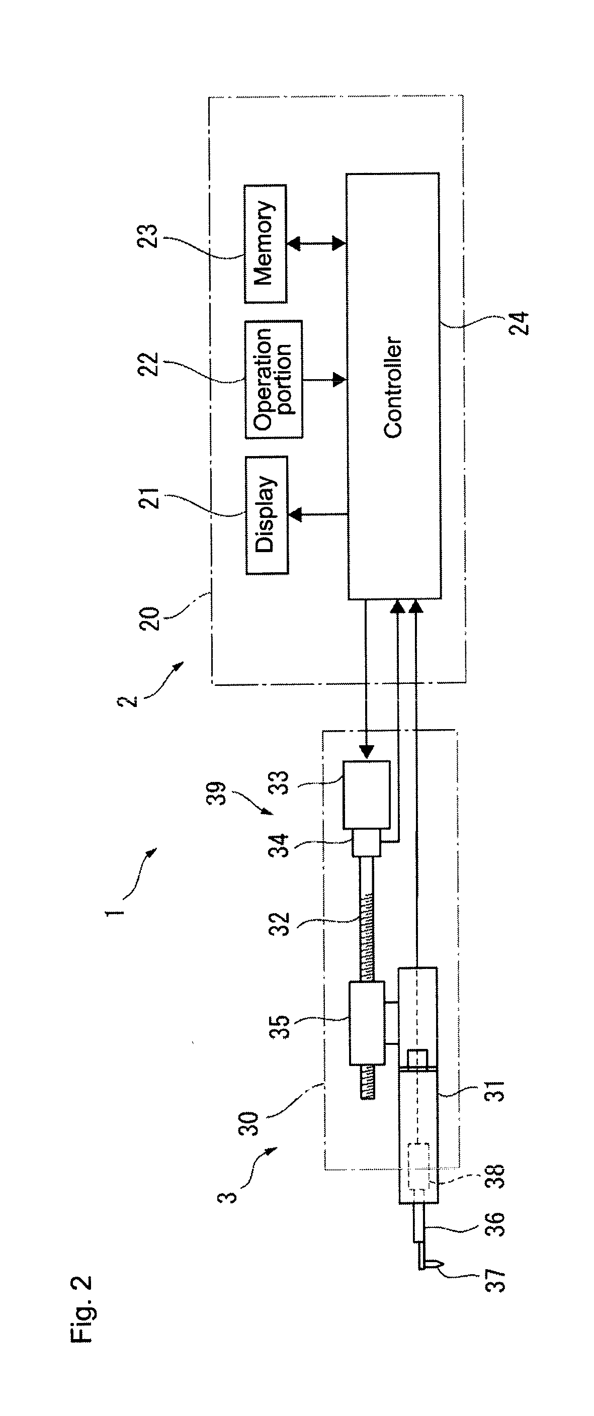
[0039]Hereinafter, an embodiment of the present invention is described with reference to the drawings. FIG. 1 is a perspective view showing an exterior of a portable surface texture measurement device. FIG. 2 shows an internal structure of the measurement device. As shown in these drawings, a surface texture measurement device...


PUM


Abstract

A surface texture measurement device displays in a display an operation screen based on display information of a current operation screen, and displays in the display a guidance screen when guidance display is requested by pressing a guidance screen display button on the operation screen. The operation screen has icon display for one or more buttons that activate predetermined functions. The guidance screen has a button list field that displays a list of icon display and function name display for the buttons included in the current operation screen and a description display field that displays a function description for any of the buttons included in the current operation screen.

Description

CROSS-REFERENCE TO RELATED APPLICATIONS[0001]The present application claims priority under 35 U.S.C. §119 of Japanese Application No. 2012-062281, filed on Mar. 19, 2012, the disclosure of which is expressly incorporated by reference herein in its entirety.BACKGROUND OF THE INVENTION[0002]1. Field of the Invention[0003]The present invention relates to a surface texture measurement device, especially a portable surface texture measurement device.[0004]2. Description of Related Art[0005]Conventionally, a surface texture measurement device has been known to measure surface texture, such as surface roughness and surface shape of a work piece (see Related Art 1, for example). The device traces a surface of the work piece with a stylus that is in contact with the surface of the work piece, displaces the stylus in a direction intersecting with a tracing direction according to the surface texture of the work piece, and measures the surface texture of the work piece based on a displacement a...

Claims


Application Information

Patent Timeline
IPC IPC(8): G06F3/0481G06F3/048G06F3/0482
CPCG06F3/04817G01B21/30G06F3/0481G05B2219/23258G01B7/34G05B19/0426G06F8/34
Inventor FUKUDA, MEGUMIHIDAKA, HIROYUKI
Owner MITUTOYO CORP
Learn More