Humidifying apparatus

a technology of humidifying apparatus and humidifier, which is applied in the direction of machines/engines, combustion-air/fuel-air treatment, energy-based chemical/physical/physico-chemical processes, etc., can solve the problems of mist emission into the environment, and achieve the effect of compact appearance, compact appearance and compact appearance of humidifying apparatus

Active Publication Date: 2013-09-26
DYSON TECH LTD
View PDF10 Cites 51 Cited by
  • Summary
  • Abstract
  • Description
  • Claims
  • Application Information

AI Technical Summary

Benefits of technology

[0006]The invention can enable a humidifying apparatus to have a compact appearance through both irradiating and atomizing water stored within a common reservoir. To enable the number of bacteria within the stored water to be reduced before the atomization of the stored water commences, there is a delay between the irradiation of the stored water with UV radiation and the commencement of the atomization of the stored water to humidify the air flow conveyed over the reservoir. During the period of time in which the irradiation is performed prior to the atomization of stored water, the water stored in the reservoir is agitated to generate a flow or swirl of water within the reservoir, and which conveys water through the UV radiation emitted into the reservoir. This can increase the volume of the stored water which is irradiated with UV radiation prior to the atomization of the stored water, and thus increase the rate of reduction of the number of bacteria within the water stored in the reservoir.
[0040]The water tank may comprise a handle which is moveable between a stowed position and a deployed position to facilitate the removal of the water tank from the base. The water tank may comprise a spring or other resilient element for urging the handle towards the deployed position. As the nozzle is replaced on the body, the nozzle may engage the handle to move the handle, against the biasing force of the resilient element, towards its first position. As the handle moves towards the stowed position, the handle may engage the catch to urge the catch away from the wedge to release the catch from its second position. The detent is preferably biased towards a deployed position for retaining the nozzle. The release of the catch from the second position can allow the detent to move automatically to its deployed position.

Problems solved by technology

The water droplets enter the flow of air passing through the air duct, resulting in the emission of a mist into the environment.

Method used


Image

  • Humidifying apparatus
  • Humidifying apparatus
  • Humidifying apparatus

Examples


Embodiment Construction

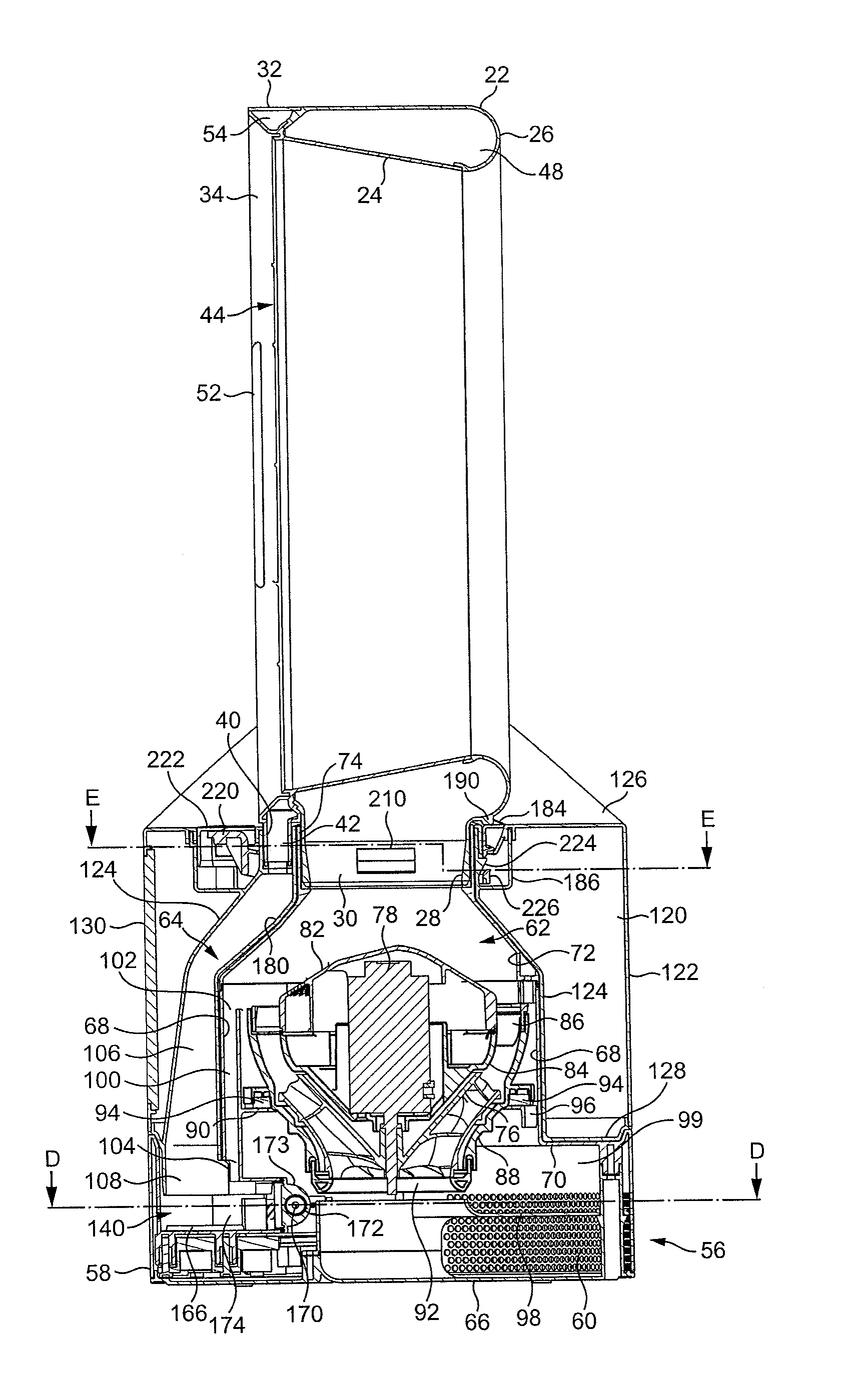
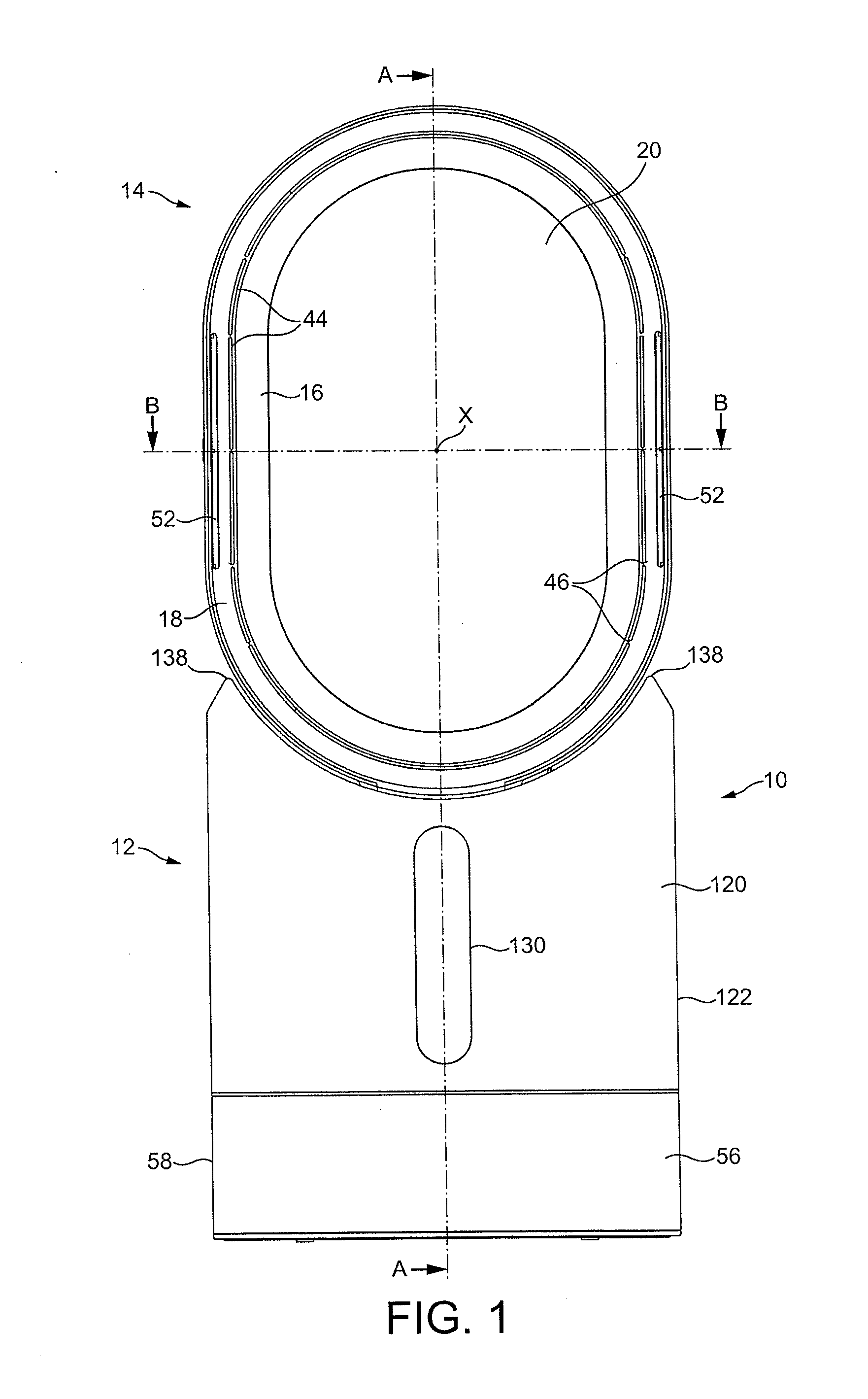
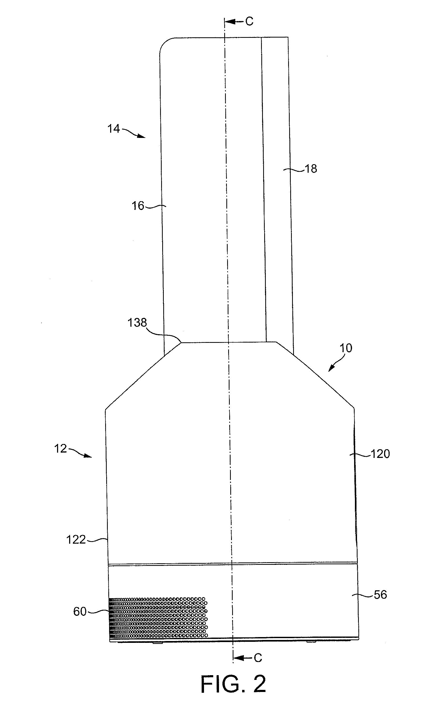
[0057]FIGS. 1 to 3 are external views of a fan assembly. In this example, the fan assembly is in the form of a humidifying apparatus 10. In overview, the humidifying apparatus 10 comprises a body 12 comprising an air inlet through which air enters the humidifying apparatus 10, and a nozzle 14 in the form of an annular casing mounted on the body 12, and which comprises a plurality of air outlets for emitting air from the humidifying apparatus 10.

[0058]The nozzle 14 is arranged to emit two different air flows. The nozzle 14 comprises a rear section 16 and a front section 18 connected to the rear section 16. Each section 16, 18 is annular in shape, and extends about a bore 20 of the nozzle 14. The bore 20 extends centrally through the nozzle 14 so that the centre of each section 16, 18 is located on the axis X of the bore 20.

[0059]In this example, each section 16, 18 has a “racetrack” shape, in that each section 16, 18 comprises two, generally straight sections located on opposite side...


PUM


Abstract

A humidifying apparatus includes a nozzle and a base on which the nozzle is mounted. The nozzle has respective first and second air inlets, air outlets and interior passages for conveying air therefrom and thereto. The nozzle defines a bore through which air outside the humidifying apparatus is drawn by air emitted from the air outlets. The base generates first and second air flows through the respective first and second interior passages, and a water reservoir. First and second air passageways convey the first and second air flows to the respective first and second air inlets. As the second air passageway conveys the second air flow over the water in the reservoir, water stored in the reservoir is agitated. An ultraviolet radiation generator irradiates the agitated water for a period of time before water stored in the reservoir is atomized to increase the humidity of the second air flow.

Description

REFERENCE TO RELATED APPLICATIONS[0001]This application claims the priority of United Kingdom Application No. 1203889.9, filed Mar. 6, 2012, the entire contents of which are incorporated herein by reference.FIELD OF THE INVENTION[0002]The present invention relates to a humidifying apparatus, and to a method of generating a humid air flow. In a preferred embodiment, the present invention provides a humidifying apparatus for generating a flow of moist air and a flow of air for dispersing the moist air within a domestic environment, such as a room, office or the like.BACKGROUND OF THE INVENTION[0003]Domestic humidifying apparatus is generally in the form of a portable appliance having a casing comprising a water tank for storing a volume of water, and a fan for creating a flow of air through an air duct of the casing. The stored water is conveyed, usually under gravity, to an atomizing device for producing water droplets from the received water. This device may be in the form of a heat...

Claims


Application Information

Patent Timeline
Patent Type & Authority Applications(United States)
IPC IPC(8): F24F6/14
CPCF24F3/16F24F6/12Y02B30/80F24F2006/125F24F6/14F24F2003/1667F24F11/62F24F11/30F24F11/70C02F1/32F04D25/08F04F5/16F04F5/46F24F8/22B01J19/10F04D29/441F04D29/545F04F5/20F24F3/14F24F11/64F24F8/80F24F2006/143F24F2006/008F24F2006/006Y02B30/70B01F25/00
Inventor STANIFORTH, MARK JOSEPHBEAVIS, DANIEL JAMESPULLEN, JUDE PAUL
Owner DYSON TECH LTD
Why Eureka
Try Eureka