Motor

a motor and motor core technology, applied in the direction of windings, magnetic circuit rotating parts, magnetic circuit shapes/forms/construction, etc., can solve the problems of wasting electricity, shading coil motors consume and waste a lot of electricity, shading coil motors are difficult to control, etc., to improve the strength of the stator core, improve the efficiency of the motor, and minimize the effect of leakage flux

Active Publication Date: 2008-06-12
LG ELECTRONICS INC
View PDF26 Cites 9 Cited by
  • Summary
  • Abstract
  • Description
  • Claims
  • Application Information

AI Technical Summary

Benefits of technology

[0018]Here, the extension part secures an enough space for a magnetic flux to flow, such that efficiency of the motor is enhanced. Also, the extension part may convexly extend to the tooth part and may improve the strength of the stator core.
[0019]A plurality of unit stator cores may be multi-layered to form the stator core. In other words, the unit stator cores may be multi-layered in a direction of a shaft, that is, a longitudinal direction. This multi-layered structure may minimize a leakage flux, which may be generated in a direction perpendicular to a flux direction, such that the efficiency of the motor is improved.
[0020]By the way, a caulking part may be formed to fasten the multi-layered unit stator cores as one body. The caulking part prevents the efficiency of motor from deteriorating. Preferably, the caulking part is formed on the extension part to prevent the structural strength of the stator core from deteriorating. The caulking part is formed on the extension part having an enough predetermined thickness. Thus, it is preferred that the caulking part is formed at a center of the extension part that has the thickest thickness.

Problems solved by technology

When the rotor is rotating, the shading coil is no longer needed and wastes electricity.
However, usually the shading coil motor consumes and wastes a lot of electricity.
Also, it is difficult to control the shading coil motor and there is a further disadvantage of being large size.
If the rotor should move along the shaft due to vibration, the PCB may be damaged.
Thereby, the strength of the outermost portion of the PCB may deteriorate.
However, in this case, the PCB getting too large may cause a problem in that the external size of the motor becomes large.

Method used


Image

  • Motor
  • Motor
  • Motor

Examples


Embodiment Construction

[0056]Reference will now be made in detail to the preferred embodiments of the present invention, examples of which are illustrated in the accompanying drawings. Wherever possible, the same reference numbers will be used throughout the drawings to refer to the same or like parts.

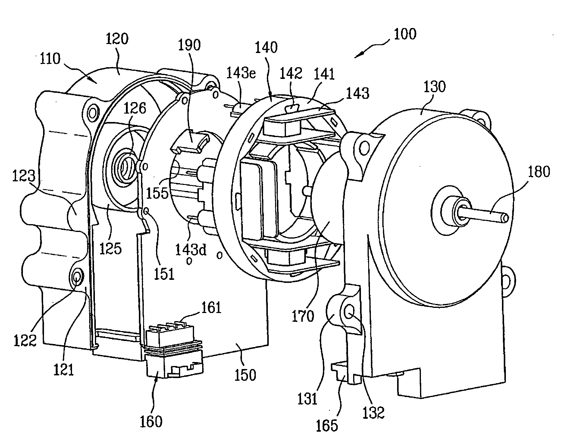
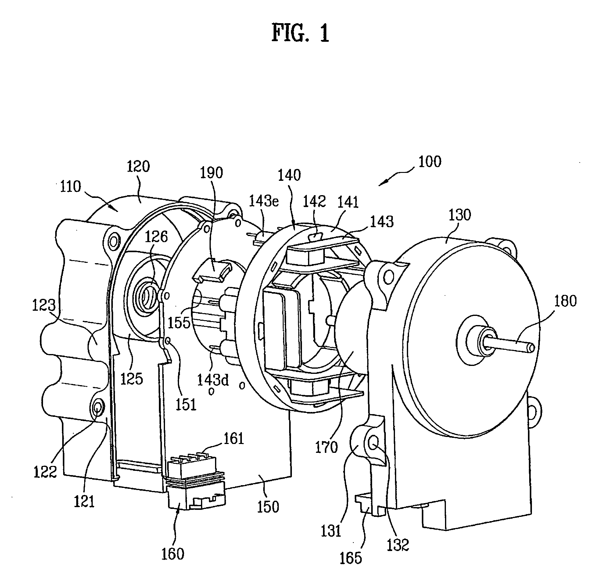
[0057]FIG. 1 is an exploded perspective view of a motor 100 according to an embodiment of the present invention.

[0058]As shown in FIG. 1, a motor includes a bracket 110, a PCB (printed circuit board) 150, a stator 140, a rotor 170 and a shaft 180. The bracket 110 defines an exterior of the motor. The PCB 150 is held within the bracket 110 and has a circuit pattern (not shown). Also, various elements (not shown) are mounted in the PCB 150.

[0059]The bracket 110 includes a lower bracket 120 and an upper bracket 130. The lower and upper brackets 120 and the 130 are coupled to each other to hold various components therein. To couple the lower and upper brackets 120 and 130 to each other, fastening bosses 121 and ...


PUM


Abstract

A motor includes a bracket that defines an exterior of the motor. A PCB is held within the bracket and has a circuit pattern and various elements mounted thereon. A stator is provided on the PCB and a rotor is provided within the stator. A shaft rotates together with the rotor to transmit a rotational force of the rotor. A stopper projects from an inside of the bracket to prevent the rotor from moving along the shaft.

Description

[0001]This application claims the benefit of the Patent Korean Application Nos. 10-2006-0122998, 10-2006-0122999, and 10-2006-0123001, all filed on Dec. 6, 2006, which are hereby incorporated by reference as if fully set forth herein.BACKGROUND OF THE INVENTION[0002]1. Field of the Invention[0003]The present invention relates to a motor, more particularly, to a motor that is easily fabricated with enhanced efficiency and durability, and which has a compact structure convenient to a user.[0004]2. Discussion of the Related Art[0005]Generally, a shading coil motor is used in to a refrigerator or a freezer as a fan motor. A shading coil as well as a main coil is wound around a stator in the shading coil motor.[0006]The shading coil is configured to start a rotor. The shading coil, together with the main coil, forms an oval shaped magnetic field to start the rotor. When the rotor is rotating, the shading coil is no longer needed and wastes electricity.[0007]Moreover, auxiliary teeth shou...

Claims


Application Information

Patent Timeline
Patent Type & Authority Applications(United States)
IPC IPC(8): H02K11/00H02K5/00H02K1/28
CPCH02K1/148H02K1/185H02K11/0073H02K5/225H02K3/522H02K11/33
Inventor LEE, HO JAE
Owner LG ELECTRONICS INC
Why Eureka
Try Eureka