Flux-switching linear permanent magnet machine with yokeless translator

a permanent magnet machine and translator technology, applied in the direction of dynamo-electric machines, electrical apparatus, manufacturing stator/rotor bodies, etc., can solve the problems of poor thrust versus current linearity characteristics, high detent force, and high cost of driv

Active Publication Date: 2013-09-26
RENESSELAER POLYTECHNIC INST
View PDF10 Cites 61 Cited by
  • Summary
  • Abstract
  • Description
  • Claims
  • Application Information

AI Technical Summary

Problems solved by technology

For long-stroke applications, these drives become very expensive.
In addition, existing linear machines exhibit poor performance opera...

Method used


Image

  • Flux-switching linear permanent magnet machine with yokeless translator
  • Flux-switching linear permanent magnet machine with yokeless translator
  • Flux-switching linear permanent magnet machine with yokeless translator

Examples


embodiment 1

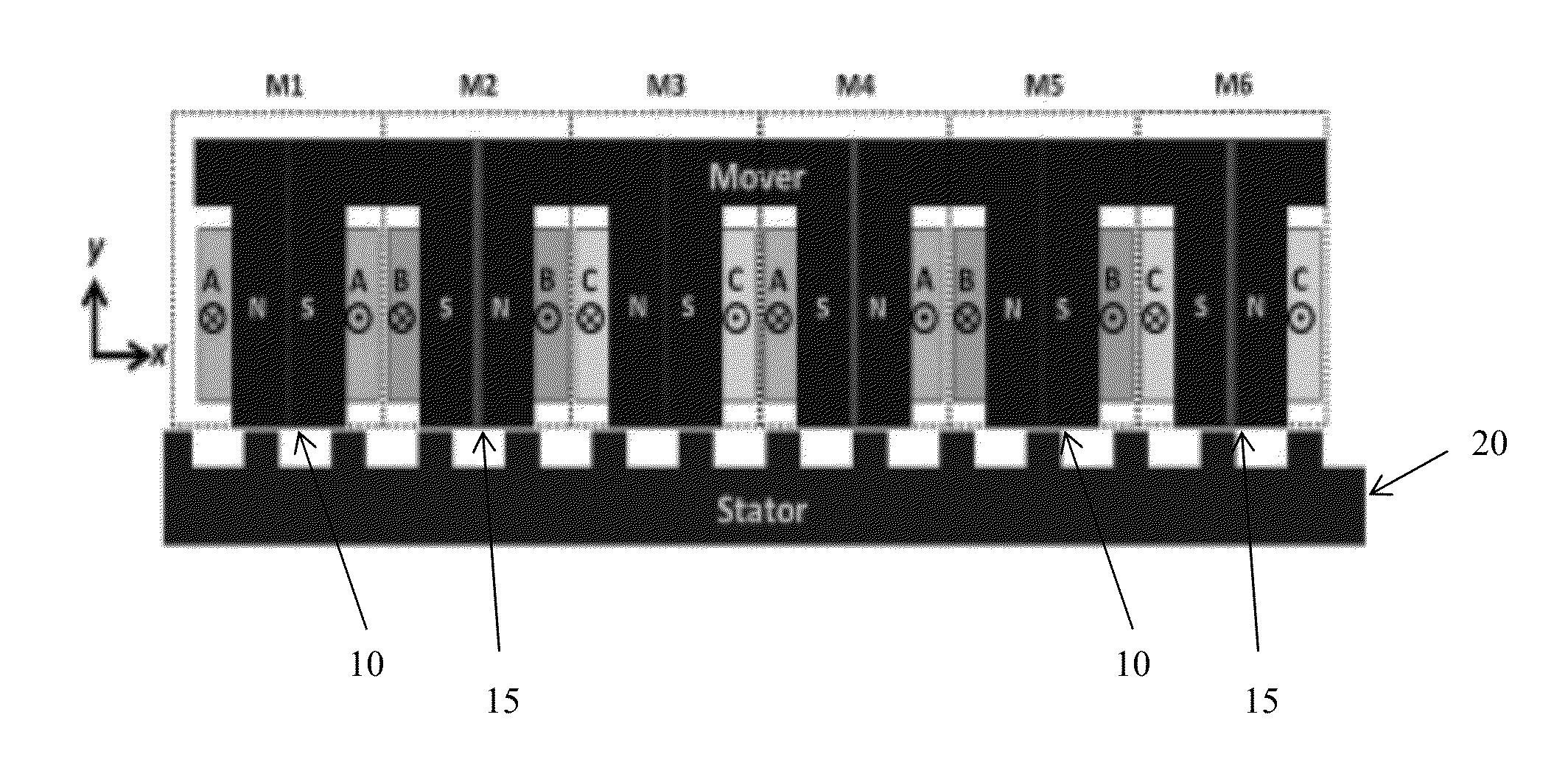
[0167]A flux-switching linear synchronous motor (FSLSM), comprising:[0168]at least two permanent magnets;[0169]a coil wrapped around each permanent magnet; and[0170]at least one stator,

[0171]wherein all permanent magnets of the FSLSM are magnetized in the same direction.

embodiment 2

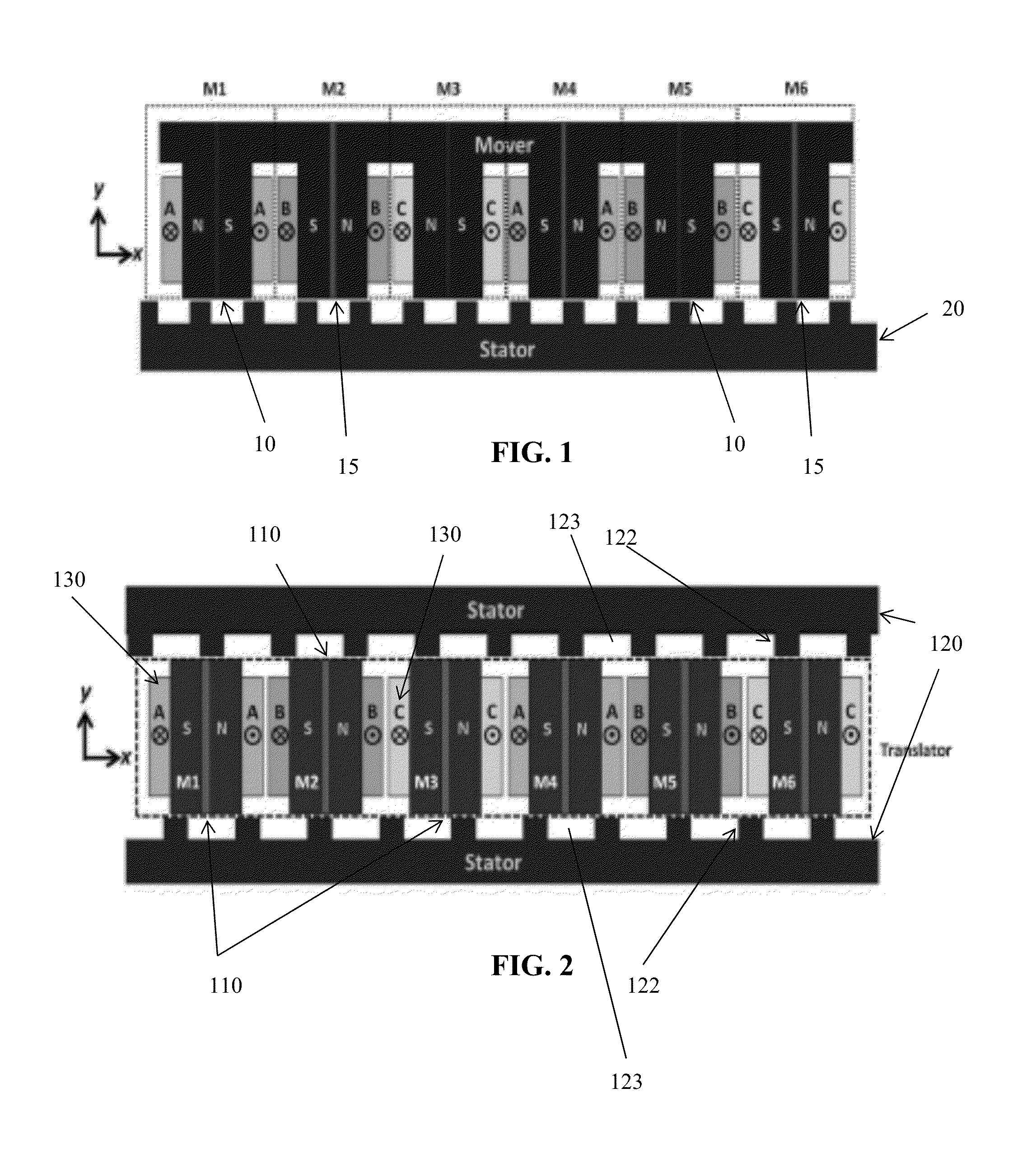
[0172]The FSLSM according to embodiment 1, comprising two stators, wherein a first stator is disposed below the permanent magnets and a second stator is disposed above the permanent magnets.

embodiment 3

[0173]The FSLSM according to embodiment 2, wherein each stator comprises stator teeth and teeth gaps between the stator teeth, wherein the first stator and the second stator are displaced from each other by half a pole pitch such that the stator teeth of the first stator are aligned with the teeth gaps of the second stator and the stator teeth of the second stator are aligned with the teeth gaps of the first stator.


PUM

PropertyMeasurementUnit
Lengthaaaaaaaaaa
Lengthaaaaaaaaaa
Lengthaaaaaaaaaa

Abstract

Advantageous motors, such as flux-switching linear synchronous motors (FSLSMs) are provided. In an FSLSM, all magnets can be magnetized in the same direction. In addition, an FSLSM can be yokeless and can have two stators displaced from one another by half a pole pitch. FSLSMs of the subject invention are cost-effective and provide high thrust, and can operate well even under fault conditions.

Description

CROSS-REFERENCE TO RELATED APPLICATION[0001]The present application claims the benefit of U.S. Provisional Application Ser. No. 61 / 631,512, filed Jan. 4, 2012, which is hereby incorporated by reference herein in its entirety, including any figures, tables, and drawings.GOVERNMENT SUPPORT[0002]The subject invention was made with government support under a research project supported by the Office of Naval Research Award No. N00014-09-1-0886. The government has certain rights in this invention.BACKGROUND[0003]Direct-drive linear machines have been used more frequently in several areas, including in industrial applications. Recent trends have led to such machines being used in place of more traditional hydraulic, pneumatic, or geared electric actuators when linear motion is desired. Typical linear motors have the magnets in the translator and the windings in the stator or vice versa. For long-stroke applications, these drives become very expensive.[0004]In addition, existing linear mach...

Claims


Application Information

Patent Timeline
IPC IPC(8): H02K41/03H02K15/03
CPCH02K41/033Y10T29/49009H02K15/03
Inventor GANDHI, ARUNPARSA, LEILA
Owner RENESSELAER POLYTECHNIC INST
Why Eureka
Try Eureka