Multi-mode power amplifier architecture

a power amplifier and multi-mode technology, applied in the field of radio frequency duplexers, can solve the problems of difficult to provide the required isolation between transmit and receive signals, difficulty in providing the required transmit and receive passbands with minimal insertion loss, and the development of wireless communication systems

Active Publication Date: 2013-09-26
QORVO US INC
View PDF12 Cites 25 Cited by
  • Summary
  • Abstract
  • Description
  • Claims
  • Application Information

AI Technical Summary

Benefits of technology

[0008]In one embodiment of the RF circuitry, the power directing circuitry either directs a driver stage output signal from the TDD / FDD driver stage to the FDD final stage or directs the driver stage output signal to the TDD final stage based on a selected operating mode of the RF circuitry. As such, the RF circuitry is capable of providing multi-mode functionality. In an alternate embodiment of the RF circuitry, the RF circuitry further includes RF bypass circuitry coupled to an output from the TDD / FDD driver stage. The TDD final stage provides a first RF output signal, the FDD final stage provides a second RF output signal, or the TDD / FDD driver stage provides a third RF output signal based on the selected operating mode of the RF circuitry. As such, the RF circuitry is capable of providing additional multi-mode functionality.

Problems solved by technology

Some communications protocols, such as specific Universal Mobile Telecommunications System (UMTS) bands have duplex gaps that are narrow relative to the transmit and receive passbands; therefore, providing the required transmit and receive passbands with minimal insertion loss while providing required isolation between transmit and receive signals may be difficult.
Additionally, as wireless communications technologies evolve, wireless communications systems become increasingly sophisticated.

Method used


Image

  • Multi-mode power amplifier architecture
  • Multi-mode power amplifier architecture
  • Multi-mode power amplifier architecture

Examples


Embodiment Construction

[0037]The embodiments set forth below represent the necessary information to enable those skilled in the art to practice the invention and illustrate the best mode of practicing the invention. Upon reading the following description in light of the accompanying drawing figures, those skilled in the art will understand the concepts of the invention and will recognize applications of these concepts not particularly addressed herein. It should be understood that these concepts and applications fall within the scope of the disclosure and the accompanying claims.

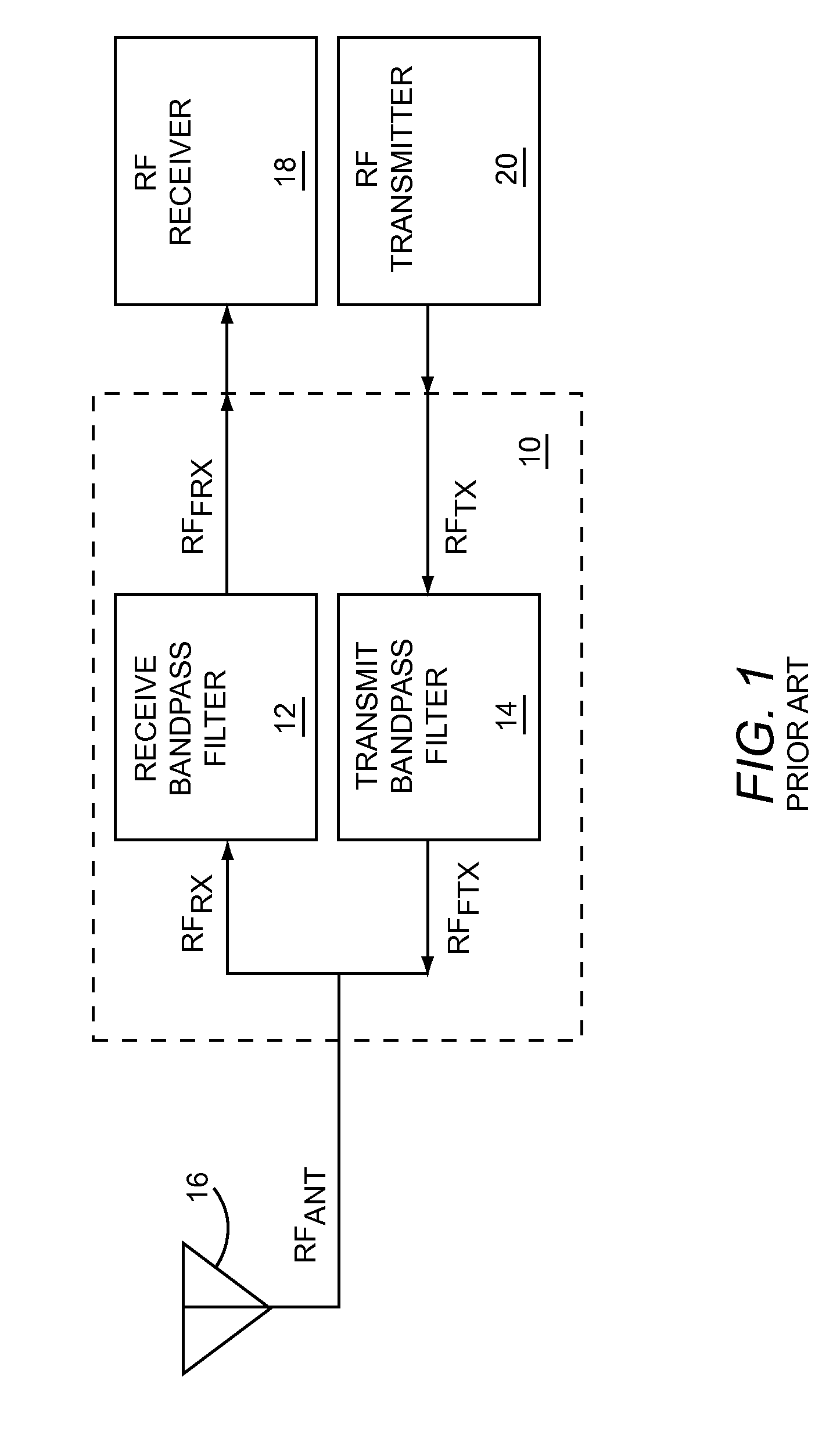
[0038]FIG. 1 shows an RF duplexer 10 according to the prior art. The RF duplexer 10 includes a receive bandpass filter 12 and a transmit bandpass filter 14, which are both coupled to an antenna 16. The antenna 16 has an antenna signal RFANT, which provides a receive signal RFRX to the receive bandbass filter 12, and receives a filtered transmit signal RFFTX from the transmit bandpass filter 14. The receive bandpass filter 12 provi...


PUM


Abstract

Radio frequency (RF) circuitry, which includes a time division duplex (TDD) / frequency division duplex (FDD) driver stage, a TDD final stage, an FDD final stage, and power directing circuitry, is disclosed. The power directing circuitry is coupled between the TDD / FDD driver stage and the TDD final stage, and is further coupled between the TDD / FDD driver stage and the FDD final stage.

Description

RELATED APPLICATIONS[0001]The present application claims priority to and is a continuation-in-part of U.S. patent application Ser. No. 13 / 732,935, filed Jan. 2, 2013, entitled “MULTI-MODE SPLIT BAND DUPLEXER ARCHITECTURE.” U.S. patent application Ser. No. 13 / 732,935, filed Jan. 2, 2013, claims priority to and is a continuation of U.S. patent application Ser. No. 12 / 899,632, now U.S. Pat. No. 8,369,250, filed Oct. 7, 2010, entitled “MULTI-MODE SPLIT BAND DUPLEXER ARCHITECTURE,” which claims priority to U.S. Provisional Patent Application No. 61 / 249,458, filed Oct. 7, 2009.[0002]All of the applications listed above are hereby incorporated herein by reference in their entireties.FIELD OF THE INVENTION[0003]The present invention relates to radio frequency (RF) duplexers, which may be used in RF communications circuitry.BACKGROUND OF THE INVENTION[0004]RF communications systems typically communicate using at least one of three different modes of operation. The first mode, called simplex,...

Claims


Application Information

Patent Timeline
Patent Type & Authority Applications(United States)
IPC IPC(8): H04L5/18
CPCH04B1/0057H04L5/18H04L5/14
Inventor KHLAT, NADIM
Owner QORVO US INC
Why Eureka
Try Eureka