
Compact image forming apparatus with simplified cover

Active Publication Date: 2013-09-26
RICOH KK
View PDF7 Cites 0 Cited by
  • Summary
  • Abstract
  • Description
  • Claims
  • Application Information

AI Technical Summary

Benefits of technology

The present invention is an image forming apparatus that has a structure for forming images, a pivotally attached cover, and an opening angle restricting device. The opening angle restricting device includes a member that contacts the cover to prevent it from spinning in the opening direction. This invention provides a novel way to prevent accidental opening of the cover and ensures safe and secure use of the image forming apparatus.

Problems solved by technology

Therefore, to attach and detach the photoconductor unit to and from the structure while preventing the photoconductor unit from interfering with the damper, the sum of a width of the photoconductor unit and the width of the damper is required as a width of the structure, thereby enlarging the image forming apparatus as a problem.

Method used


Image

  • Compact image forming apparatus with simplified cover
  • Compact image forming apparatus with simplified cover
  • Compact image forming apparatus with simplified cover

Examples


Embodiment Construction

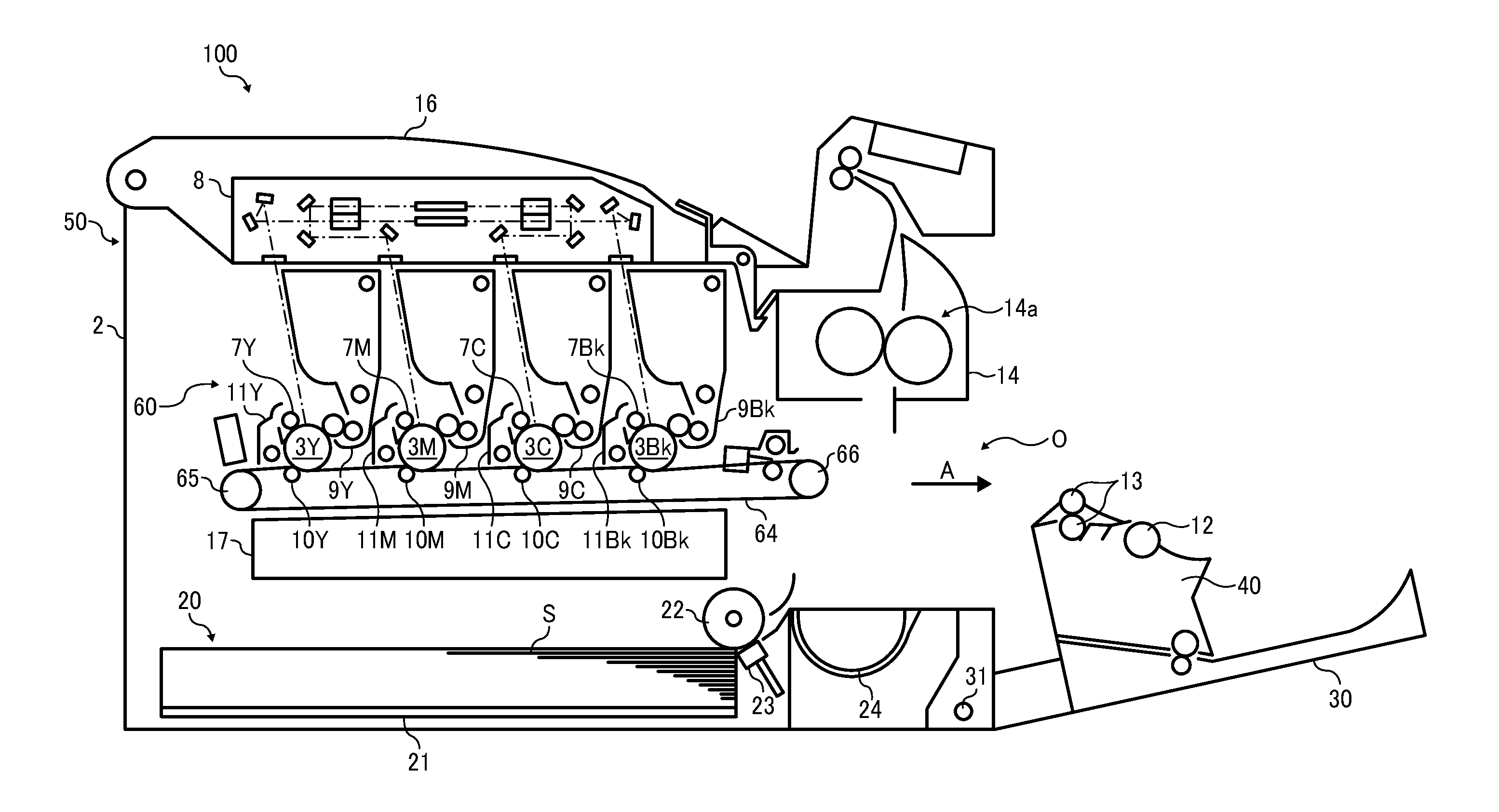
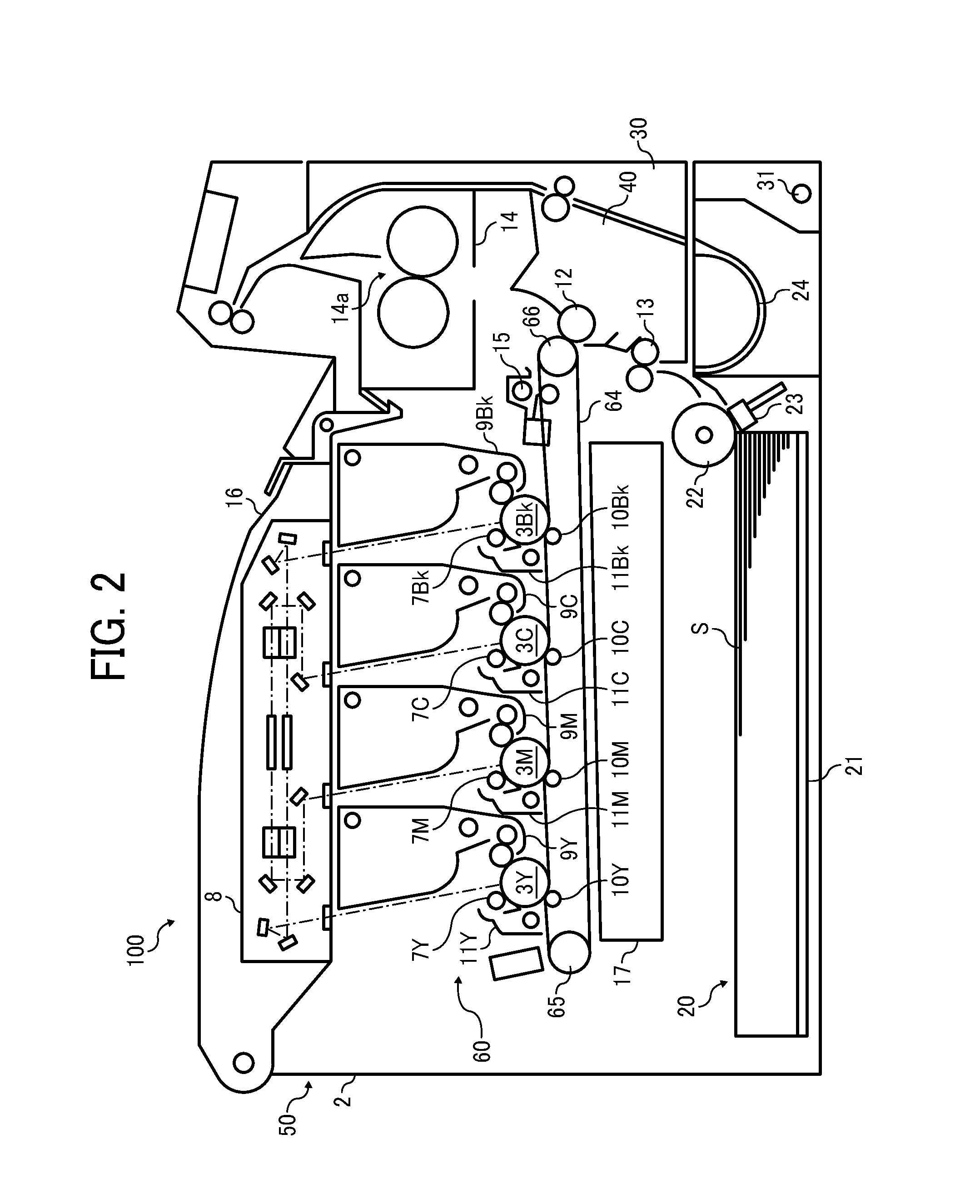
[0042]Referring now to the drawings, wherein like reference numerals designate identical or corresponding parts throughout the several views thereof and in particular to FIG. 2, a schematic configuration of a printer 100 as an image forming apparatus according to one embodiment of the present invention is described. The printer 100 of this embodiment is a color printer of a tandem type with an image forming unit 60 located at a center of an apparatus main body 50 and a sheet feeding unit 20 located below the image forming unit 60 to feed a sheet to form an image thereon by the image formation unit 60.

[0043]In the image formation unit 60, multiple drum-shaped photoreceptors 3Y, 3M, 3C, and 3Bk are provided as image carriers. Each of the photoreceptors 3Y, 3M, 3C, and 3Bk forms a toner image having a different color. In an illustrated example, yellow, cyan, magenta, and black toner images are formed in respective surfaces of the photoreceptors 3Y, 3C, 3M, and 3Bk. Each of the photorec...


PUM


Abstract

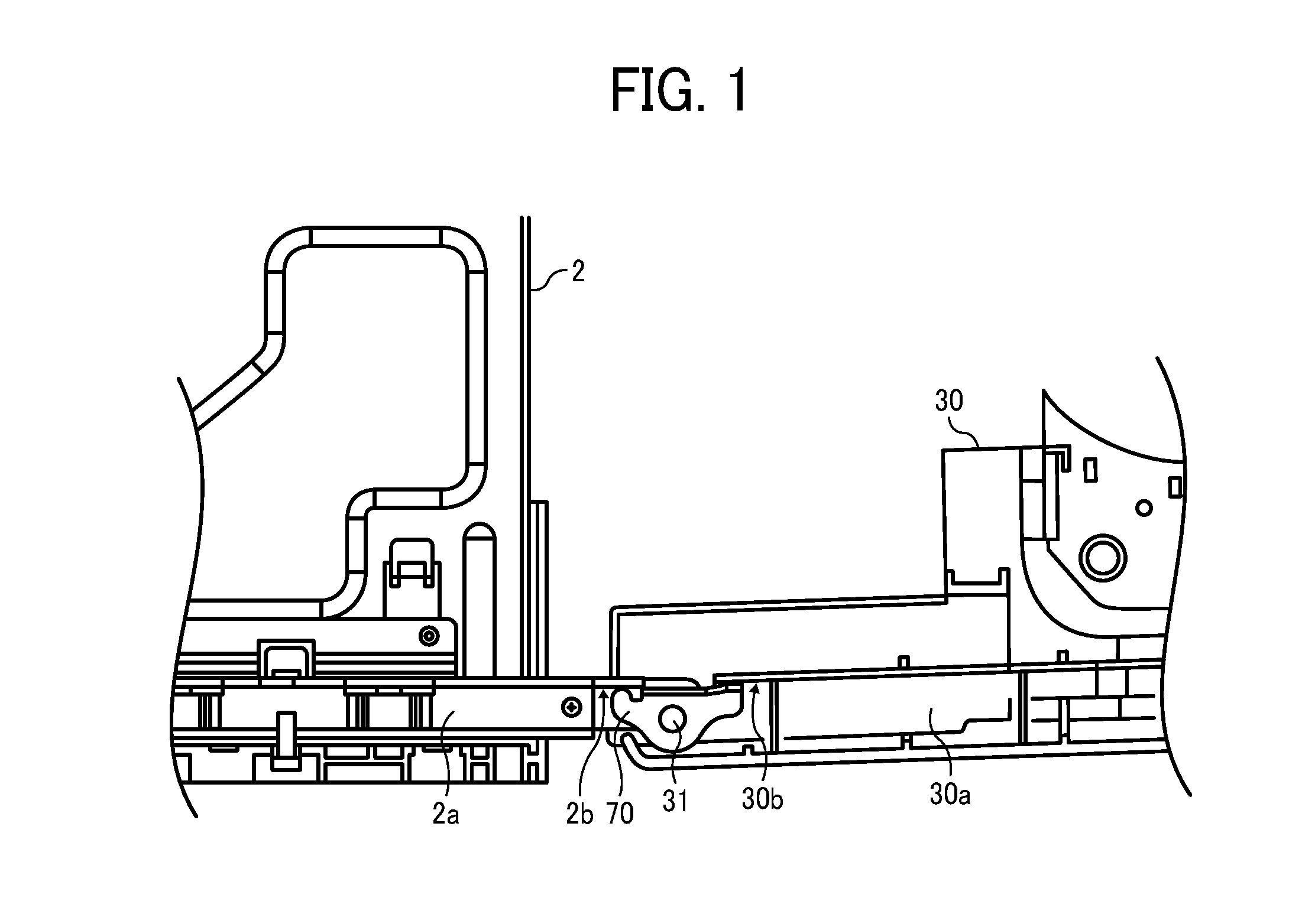
An image forming apparatus includes a structure having an image formation device to form an image, a cover pivotally attached to the structure around a rotary shaft, and an opening angle restricting device to restrict an opening angle of the cover regarding the structure. The opening angle restricting device includes a pivotable cover rotation restriction member coaxially arranged with the rotary shaft to contact a downstream side of the pivotable cover in a cover opening direction at its first end to restrict the rotation of the pivotable cover in the opening direction.

Description

CROSS-REFERENCE TO RELATED APPLICATION [0001]This patent application is based on and claims priority pursuant to 35 U.S.C. §119 to Japanese Patent Application No. 2012-064802, filed on Mar. 22, 2012 in the Japan Patent Office, the entire disclosure of which is hereby incorporated by reference herein.BACKGROUND [0002]1. Technical Field[0003]The present invention relates to an image forming apparatus, such as a copier, a printer, a facsimile machine, etc.[0004]2. Related Art[0005]In a conventional image forming apparatus, an image forming unit, such as a photoconductor unit, an intermediate transfer unit, etc., is included in a structure of an apparatus main body and is attached and detached to and from the structure by opening a pivotable cover to execute maintenance and replacement of the image forming unit or the like.[0006]According to an image forming apparatus described in Japanese Patent Application Publication No. 2010-14813 (JP-2010-14813-A), by opening a pivotable cover open...

Claims


Application Information

Patent Timeline
IPC IPC(8): G03G15/00
CPCG03G21/1633
Inventor FUJIMOTO, TAKASHI
Owner RICOH KK
Learn More