Camera mount

a technology for mounting brackets and cameras, applied in washstands, lighting support devices, instruments, etc., can solve problems such as restricting the removal of plates from the base, and achieve the effect of widening the entry point of sockets

Active Publication Date: 2013-10-03
KESSLER CRANE
View PDF14 Cites 41 Cited by
  • Summary
  • Abstract
  • Description
  • Claims
  • Application Information

AI Technical Summary

Benefits of technology

[0005]The present disclosure describes a quick-release camera mount which includes a plate which mounts on a base. The plate includes a pair of dovetailed legs which mate with a dovetailed socket formed in the base, resembling a sliding dovetail joint. One side of the socket is formed from a dropping gate such that the plate can be inserted onto the base in a direction perpendicular to a plane defined by the socket. Inserting the plate on the base in this manner can be referred to as “vertical insertion.” As the plate is inserted onto the base, the dropping gate recedes into a compartment which effectively widens the point of entry of the socket, allowing the dovetailed legs to be inserted into the socket. Once the plate is fully inserted, the dropping gate springs up from the compartment and overlies one of the dovetailed legs of the plate, thereby restricting removal of the plate from the base. With the plate seated on the base the plate is slideable along a path parallel with a plane defined by the socket. The base includes a clamping apparatus used to restrict movement of the plate on the base. A stop extends from the base which prevents the plate from sliding off of the base.

Problems solved by technology

Once the plate is fully inserted, the dropping gate springs up from the compartment and overlies one of the dovetailed legs of the plate, thereby restricting removal of the plate from the base.

Method used


Image

  • Camera mount
  • Camera mount
  • Camera mount

Examples


Embodiment Construction

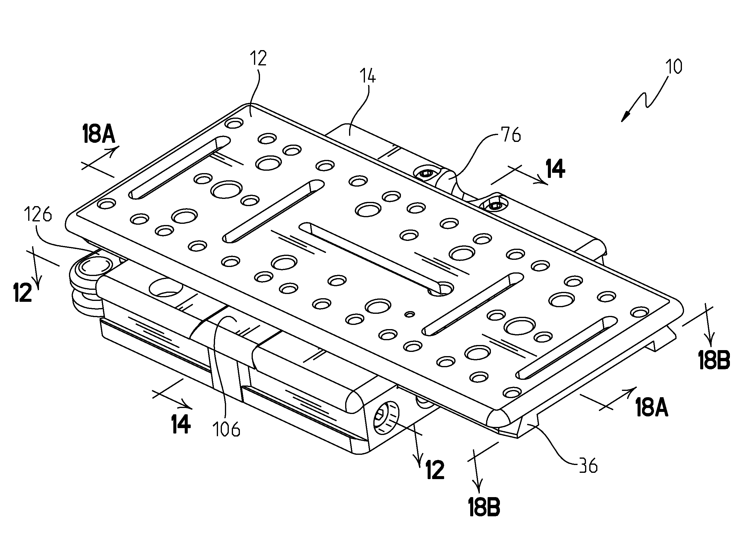
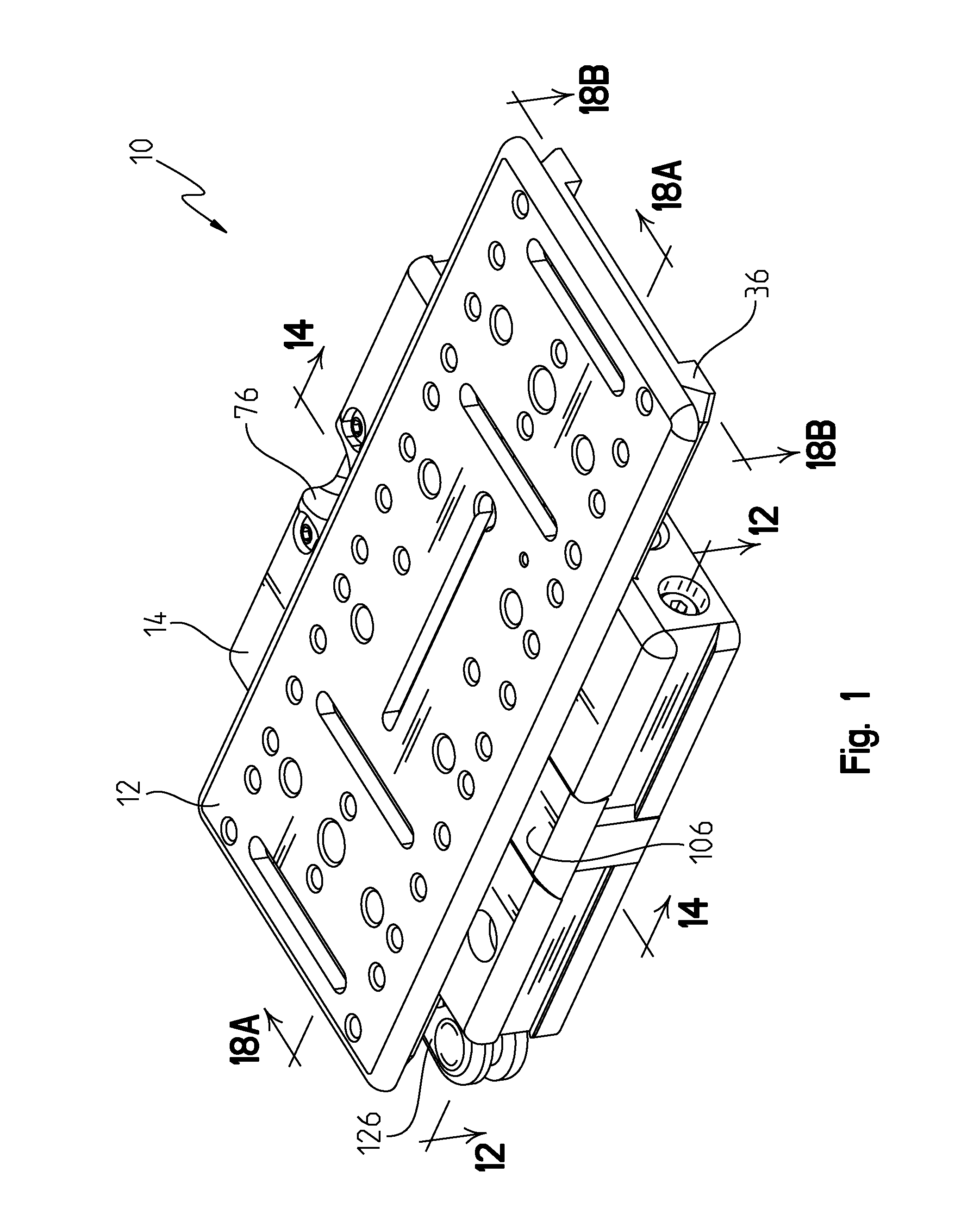
[0026]Mounting system 10 includes two main elements: a plate 12 and a base 14. Plate 12 includes a tail 36 and base 14 includes a socket 18; tail 36 and socket 18 mate together in a dovetailed-fashion to removably secure plate 12 on base 14 as shown in FIG. 1. These and other aspects of mounting system 10 will be described in detail as follows.

[0027]Mounting system 10 is described herein as used to mount a camera to a stand, but it is contemplated that the mounting system of the present disclosure has other applications. One example of a suitable alternative application is to use mounting system 10 to removably mount seats to a boat. As such, any reference herein to cameras should not be read as limiting the scope of the present disclosure.

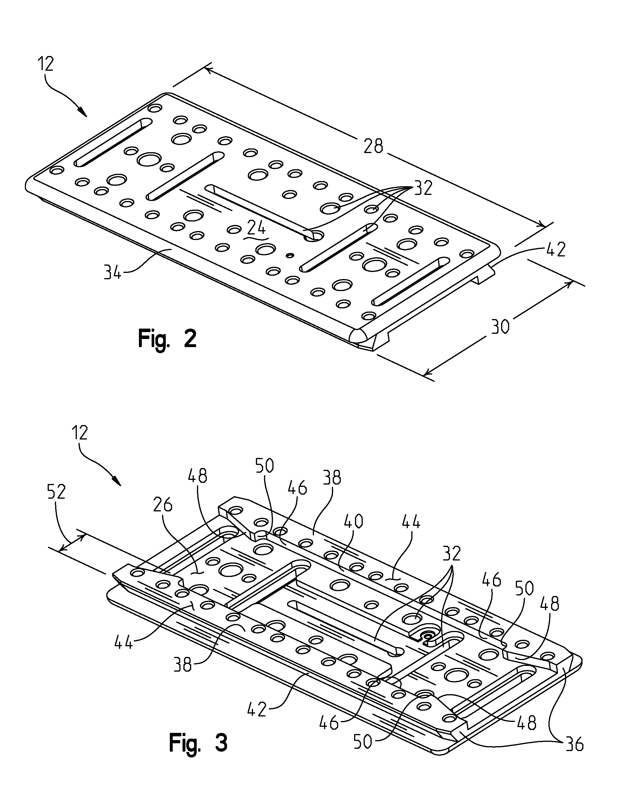
[0028]Plate 12 is a generally rectangular plate having a top side 24, a bottom side 26, a length 28 and a width 30 as shown in FIGS. 2 and 3. Top side 24 of plate 12 is a generally flat surface which includes one or more plate apertures 32 piercin...


PUM


Abstract

A mount having a plate with a tail portion and a base with a socket portion. The socket includes a dropping gate which recedes into a compartment in the base when the plate is vertically inserted on the base. The base includes a stop which engages a catch on the plate to prevent the plate from being laterally removed from the base.

Description

BACKGROUND OF THE INVENTION[0001]Photographic and video cameras, and related accessories, are often mounted to objects or stands, such as tripods, cranes and other camera-carrying objects. Many quick-release mounts are available for readily attaching and detaching a camera from a stand and typically include a plate / base pair where the plate is attachable to a camera body and the base is attachable to a stand and the plate and base feature connective members which readily attach and detach from one another.[0002]Most quick-release mounting plates include a dovetailed tail which slides into a dovetailed socket on the base. Generally, the plate is inserted onto the base by sliding the dovetailed tail of the plate into one side of the dovetailed socket on the base, then sliding the plate along the socket to a desired position where it is then clamped in place with a clamping apparatus. Inserting the plate on the base in this manner can be referred to as “lateral insertion.” The clamping...

Claims


Application Information

Patent Timeline
Patent Type & Authority Applications(United States)
IPC IPC(8): G03B17/56
CPCG03B17/561F16M11/041F16M13/00F16M11/048F41G11/003F16M11/16F16M2200/028
Inventor KESSLER, ERICEGGLNK, RICHARD
Owner KESSLER CRANE
Why Eureka
Try Eureka