Button style cord connector

a cord connector and button-style technology, applied in the direction of coupling device details, coupling device connection, transportation and packaging, etc., can solve the problems of very difficult insertion and pulling out for reusability, very difficult to reuse, and very difficult to reus

Inactive Publication Date: 2008-02-19
THOMAS & BETTS INT INC
View PDF15 Cites 20 Cited by
  • Summary
  • Abstract
  • Description
  • Claims
  • Application Information

AI Technical Summary

Benefits of technology

[0023]It will therefore be seen that the present invention provides a connector for non-metallic sheathed cable that is of one piece construction and adapted for ready application to a box outlet opening utilizing the snap fit connection that has been described and illustrated, without requiring any special tools to apply the connector to the box or cable to the connector. The connector is free of clamps and other similar types of mechanical connecting devices, and no clamp acting on the cable end is required within the box in which the cable end extends. A further embodiment of the invention provides a wire connector comprising a single unit thereby avoiding the situation where the installer must field assemble or tighten multiple components together in order to complete the installation.
[0025]Yet a further embodiment of the invention is to provide a liquid-tight, strain-relief cord connector that also helps isolate and protect the wire from the sharp edges of the knock-out or opening through which the wire passes. Another embodiment of the present invention also provides a connector that not only provides strain relief, but also seals the perimeter around both the wire and the enclosure or knock-out opening through which the wire passes. The present invention also provides a connector where the strain relief and the sealing characteristics occur automatically upon wire insertion and do not require any secondary operation or installation step which would prolong the installation process.
[0026]Yet another embodiment of the invention provides a connector that is not bulky and does not project significantly from either side of the box so as to eliminate any chances of interference. Still another embodiment of the invention provides a connector that is sized slightly bigger than the opening into which it will fit. Another embodiment provides a connector that can accommodate a variety of different cord gauges without the need for the installer to keep different connector sizes in store.
[0027]A preferred embodiment of the present invention provides for very little gap center. As the tips or apex of the fingers extend closer to the center and to each other, there is very little gap between these tips and they form a tighter circle between them. A further preferred embodiment of the present invention provides for easier cable insertion by having the fingers angle away from the flange. Yet another preferred embodiment of the invention provides for higher cable retention force, because the fingers are curved inwardly, not outwardly, and cable pull-out is resisted better by the design of the preferred embodiment.
[0033]Such inventive features could be provided in a preferred embodiment of a cord connector consisting of a pliable shell having a wire passageway therethrough. Adjoining this shell is a more rigid skeleton also configured with a wire passageway therethrough. This skeleton incorporates deflectable appendages which are deflected by the passage of a wire through the wire passageway. Further, these deflectable appendages restrict the removal of the wire back through the wire passageway in the opposite direction, whereby the pliable shell seals around the wire in the wire passageway while the skeleton provides strain relief to the wire in the wire passageway.

Problems solved by technology

This makes insertion and pullout for reusage very difficult as well.
In use, once an extreme force is utilized to pull out the cable, the device, in effect, becomes very difficult to reuse and thus rendered useless.
This all leads to the design thickness being bulkier, which could cause interference with other parts in the box.
In fact, these devices are not manufactured for non-standard sizes.
And thus, this design is useful for only a limited range of cable sizes.
Hence, only when the cabling begins to flex will the fingers of the design provide pull-out resistance (it will, however, still seal the cable due to the stretching of the overmolded material).
Thus, the type of cable cross-sectioned shape of cable and its gauge that can be used is limited for the device.
In practice, moisture and debris can collect inside the device via this hole which is not desirable at all.
Thus, the device can not be used as a plug due to the device having two walls.
Although the grommet 10 of the device may be weatherproof, because the cable is supported directly by only the two flexible outer extensions, and no rigid skeleton, the connector does not provide for stability.
In tight spaces, or a wall where other side is not easily accessible, such installation can be frustrating.

Method used


Image

  • Button style cord connector
  • Button style cord connector
  • Button style cord connector

Examples


Embodiment Construction

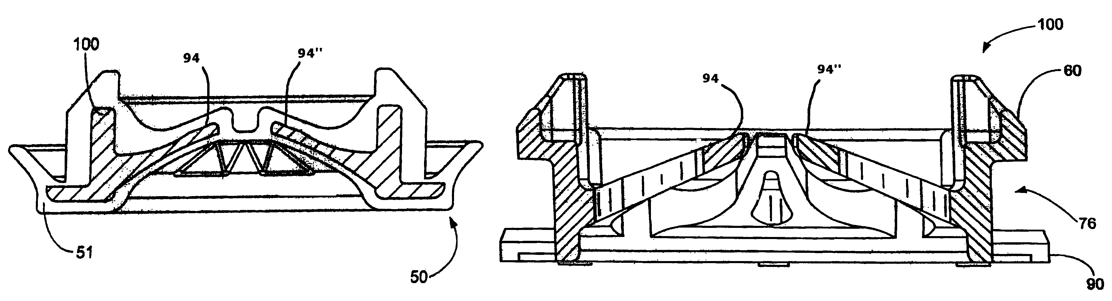
[0058]As can be seen initially in FIGS. 13, 14 and 15, reference numeral 50 generally indicates a preferred embodiment of the invention, that is shown applied to a wall 52 of a box 54 (of which only the indicated portion of wall 52 is shown), and specifically within the knock-out opening 56 that is formed in the box. The connector 50 is pushed into the knock-out or opening 56 from one side through an opening in wall 52 in the normal fashion. In essence, the connector 50 sandwiches the perimeter 57 of the knock-out opening 56 in the wall 52 between a pair of tabs 60, 60′ on one side and a rubber-coated flange 90 (over-molded by the elastomeric circumferential ledge 84 as shown) on the other. Flange 90 acts as a stop measure, preventing connector 50 from being pushed completely through the wall opening 56. The outer surface of tab 60 is inclined to ease its insertion through the opening 56. In essence, connector 50 helps isolate wire 58 from the sharp edges of the perimeter 57 of the ...


PUM


Abstract

This invention pertains to a cord connector that both seals and provides strain relief automatically upon wire insertion. The cord connector comprises a wire passageway through a pliable shell which seals around both the wire inserted through the passageway as well as the knock-out or wall opening into which the connector is secured. A more rigid skeleton supports this shell and is provided with appendages which permit the wire to pass through the passageway but which block or resist any removal of the wire from the passageway. Preferably the shell is overmolded over the skeleton for ease of manufacture.

Description

[0001]This utility application claims priority from the U.S. provisional application Ser. No. 60 / 701,415 filed on Jul. 21, 2005 which has disclosure document number T&B 1894 filed on Jul. 21, 2005 attached to it, all of which is incorporated by reference herein.FIELD OF THE INVENTION[0002]This invention, in general, pertains to cord connectors for supporting electrical wire to a wall or a panel of an enclosure. More particularly, the present invention pertains to a connector for an electric cable providing both sealing and strain relief characteristics.BACKGROUND OF THE INVENTION[0003]Liquid tight cord connectors are quite common for supporting electric wire passing through an aperture of an electrical enclosure or a wall. These cord connectors are often used to protect wires or tubes passing through such apertures against wear or shock or both.[0004]FIGS. 1-7 of U.S. Pat. No. 2,458,409 discloses a connector member with integral spring-like fingers cooperating with and preventing ax...

Claims


Application Information

Patent Timeline
Patent Type & Authority Patents(United States)
IPC IPC(8): H02G3/18
CPCB60R16/0222H02G3/088H02G3/22H02G15/013H01R13/5205H01R13/5816
Inventor PYRON, ROGERYOSS, CRAIG
Owner THOMAS & BETTS INT INC
Why Eureka
Try Eureka