
Image formation method and image formation apparatus

a technology of image formation and image, applied in the direction of electrographic process apparatus, visual presentation, instruments, etc., can solve the problems of text density extremely reduced, image hue drastically changed, text difficult to read,

Inactive Publication Date: 2013-10-03
OKI DATA CORP
View PDF5 Cites 4 Cited by
  • Summary
  • Abstract
  • Description
  • Claims
  • Application Information

AI Technical Summary

Benefits of technology

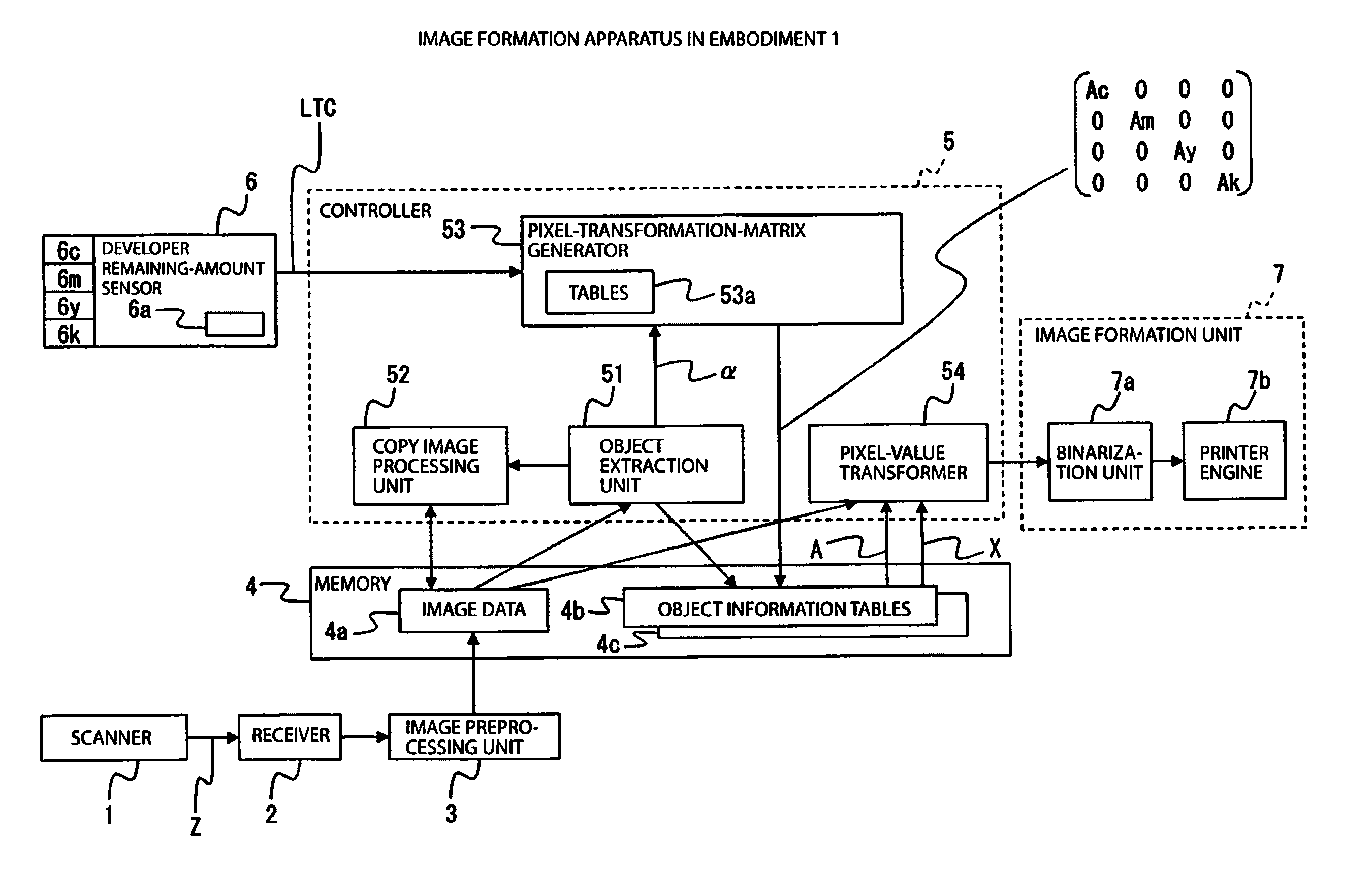
This patent invention describes a way to create images and text using developers that can be adjusted based on the type of objects in the image and the amount of developer remaining. This allows for continued image formation even when the color of the developer changes. The color of the image remains stable, the density of text color is maintained, and the readability of the text is not compromised. Overall, this invention provides a more efficient and effective way to create high-quality images and text.

Problems solved by technology

The conventional image formation method and image formation apparatus, however, have the following problems (a) and (b).
(a) Since a pixel-value transformation table for color printing has fixed values, any reduction in the use amount of a developer having a small remaining amount of developer causes an image to have a drastically changed hue and thus to appear unnatural.
(b) Since the pixel-value transformation table for color printing has fixed values, a reduction in the use amount of the developer having a small remaining amount of developer causes text to have an extremely reduced density and thus making the text difficult to read.

Method used


Image

  • Image formation method and image formation apparatus
  • Image formation method and image formation apparatus
  • Image formation method and image formation apparatus

Examples


embodiment 1

Operation in Embodiment 1

[0042]Descriptions are next given of (I) Overall operation of the image formation apparatus, (II) Method of generating the pixel transformation matrix, and (III) Image formation method.

[0043](I) Overall Operation of the Image Formation Apparatus

[0044]With reference to FIGS. 2 to 4, a description is given of an overall operation of the image formation apparatus in FIG. 1. In FIG. 1, scanner 1 reads an original image of a document, a book, a photo or the like, transforms the original image into electric signals Z and outputs electric signals Z to receiver 2. Receiver 2 transforms the inputted electric signals Z into image data expressed using the RGB color space and outputs the image data to image preprocessing unit 3. Image preprocessing unit 3 transforms the inputted RGB image data to image data 9a, expressed by using the 256 tones in the YCbCr color space, and temporarily stores image data 4a in memory 4.

[0045]Object extraction unit 51 performs the region s...

embodiment 2

Operation in Embodiment 2

[0096]An overall operation of the image formation apparatus in Embodiment 2 is the same as in (I) of Embodiment 1: Overall operation of the image formation apparatus. Thus for Embodiment 2, descriptions are given of (I) Method of generating the pixel transformation matrix and (II) Detailed operation in the image formation method.

[0097](I) Method of Generating the Pixel Transformation Matrix

[0098]How pixel-transformation-matrix generator 53A in FIG. 7 generates a pixel transformation matrix is described with reference to FIG. 8.

[0099]Pixel transformation matrix |B| in Embodiment 2 is formed by four rows and four columns like pixel transformation matrix |A| in Embodiment 1. Elements Bij (i=1, 2, 3 or 4 and j=1, 2, 3 or 4) where i≠j in the determinant take a value of 0, while elements B11, B22, B33, B44 (diagonal elements) where i=j have four transformation coefficients Bc, Bm, By, and Bk for the four colors of CMYK, respectively. That is, the pixel transformat...


PUM


Abstract

An image formation apparatus includes a memory to store image data including objects each having information on a type and densities of colors of the object, a developer-remaining-amount sensor to sense and output remaining-amount information indicating a color of a developer having a small remaining amount among colors of respective developers for image formation, a controller to transform first pixel values of the densities of the colors of each object included in the image data stored in the memory into second pixel values indicating use amounts of the colors of the developers, for each object based on the type of the object and the remaining-amount information, an image formation unit to form images on a recording medium for the objects included in the image data by using the developers in accordance with the use amounts of the developers corresponding to the second pixel values transformed by the controller.

Description

CROSS REFERENCE TO RELATED APPLICATIONS[0001]This application claims priority based on 35 USC 119 from prior Japanese Patent Application No. 2012-074155 filed on Mar. 28, 2012, entitled “IMAGE FORMATION METHOD AND IMAGE FORMATION APPARATUS”, the entire contents of which are incorporated herein by reference.1. FIELD OF THE INVENTION[0002]The disclosure relates to an image formation method and an image formation apparatus which performs image processing using a reduced amount of a developer when the remaining amount of the developer becomes small.2. DESCRIPTION OF RELATED ART[0003]Image data often includes a text object expressing letters and other symbols, and an image object expressing a half-tone image having gradations. In a known type of conventional image formation method and image formation apparatus, data for printing is obtained from such image data by changing tables for transforming pixel values depending on the object types such as text and image objects, as described in J...

Claims


Application Information

Patent Timeline
Patent Type & Authority Applications(United States)
IPC IPC(8): G06K15/00
CPCG06K15/002H04N1/00G03G15/553G03G15/5025H04N1/6072
Inventor OTSUKA, NAOKI
Owner OKI DATA CORP
Learn More