Cutting Tool Having Clamping Bolt Provided with Locking Portion and Cutting Insert Therefor

Active Publication Date: 2013-10-03
ISCAR LTD
View PDF2 Cites 17 Cited by
  • Summary
  • Abstract
  • Description
  • Claims
  • Application Information

AI Technical Summary

Benefits of technology

The present invention relates to a cutting tool comprising a cutting insert which is removably secured in a tool shank by a clamping bolt. The cutting insert has a body with a cut-out extending along a cut-out axis from a first side surface to an opposing second side surface and opening out to a bottom surface extending therebetween, with at least one undercut having an undercut sub-surface. The cutting tool also includes the clamping bolt with a bolt shank having a threaded portion and at least one bolt locking portion. The bolt shank can be rotated from a locked position to an un-locked position. The technical effect of this invention is that it provides a cutting tool with improved stability and secure mounting of the cutting insert in the tool shank.

Problems solved by technology

The cutaway portion includes no safety feature to prevent the tip from being inadvertently ‘pulled’ from the drill main body.

Method used


Image

  • Cutting Tool Having Clamping Bolt Provided with Locking Portion and Cutting Insert Therefor
  • Cutting Tool Having Clamping Bolt Provided with Locking Portion and Cutting Insert Therefor
  • Cutting Tool Having Clamping Bolt Provided with Locking Portion and Cutting Insert Therefor

Examples


Embodiment Construction

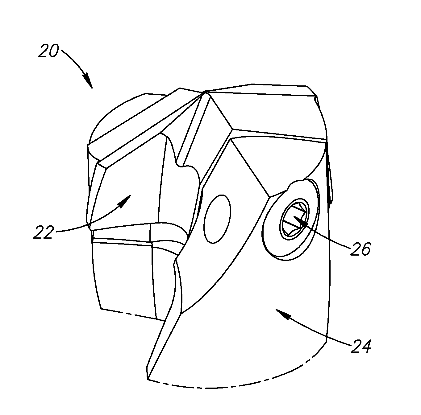
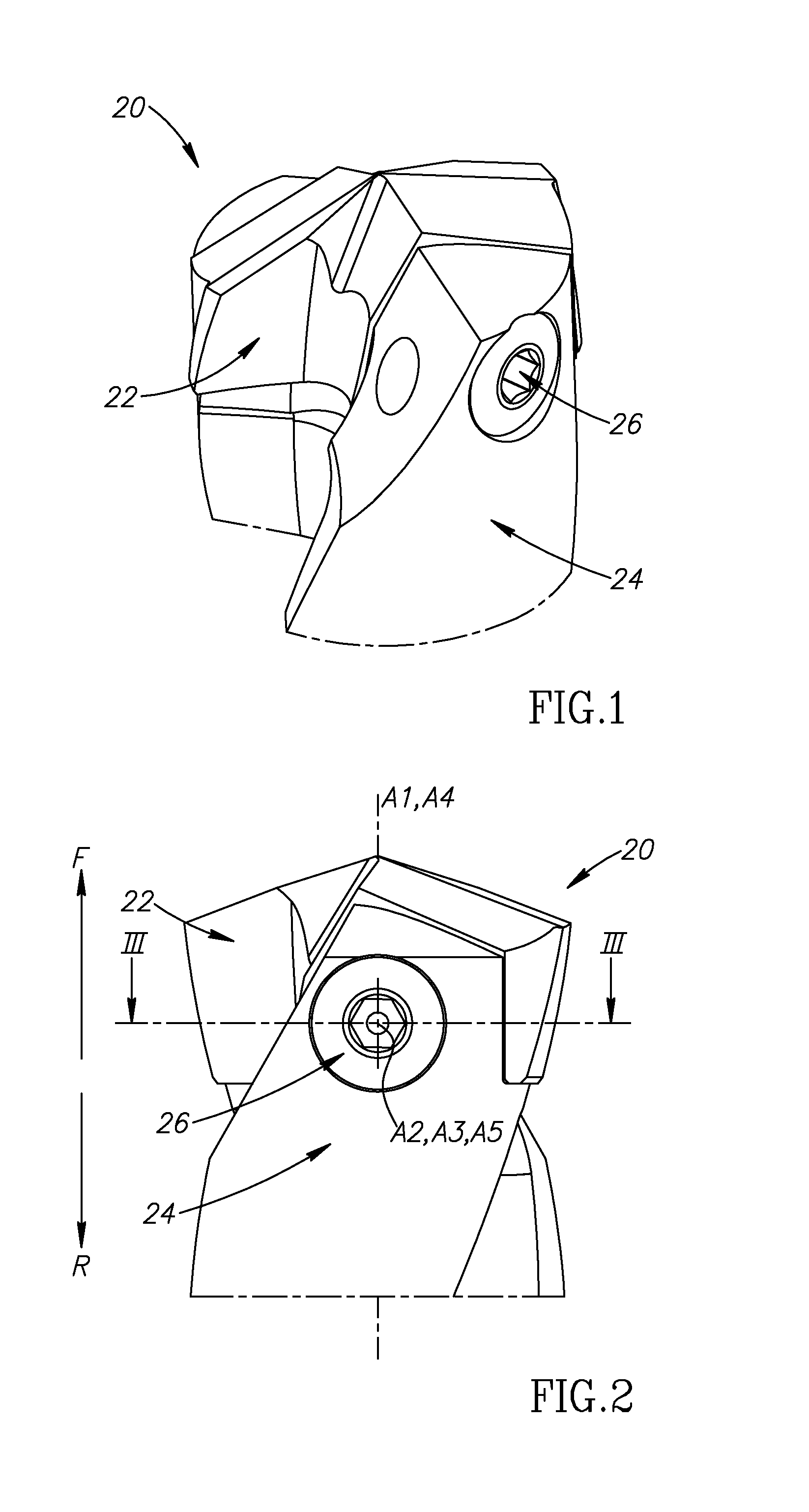
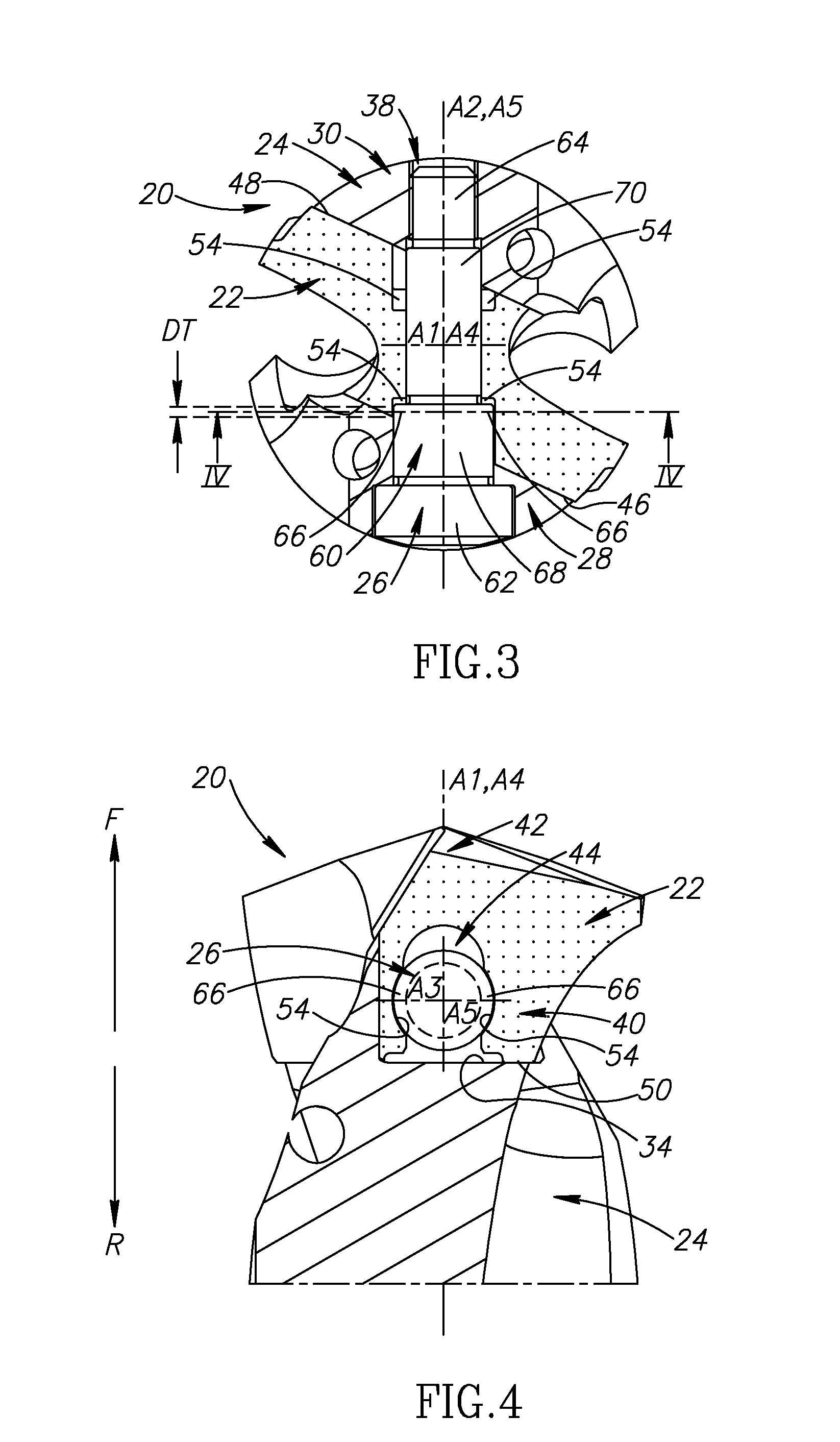
[0035]The present invention relates to a cutting tool 20 comprising a cutting insert 22 removably securable in a tool shank 24 by means of a clamping bolt 26.

[0036]In some embodiments of the present invention, the cutting tool 20 may be in the form of a rotary cutting tool. As shown in FIGS. 1 to 4, the cutting tool 20 may be in the form of a drill.

[0037]Also, in some embodiments of the present invention, the tool shank 24 may be manufactured from machined steel, and the cutting insert 22 may preferably be manufactured by form pressing and sintering a cemented carbide, such as tungsten carbide, and may be coated or uncoated.

[0038]According to the present invention, as shown in FIGS. 5 and 6, the tool shank 24 extends along a longitudinal axis A1, and has spaced apart first and second protuberances 28, 30 protruding from an end portion 32 thereof.

[0039]In some embodiments of the present invention, the first and second protuberances 28, 30 may protrude from the end portion 32 in a for...


PUM

PropertyMeasurementUnit
Angleaaaaaaaaaa

Abstract

A cutting tool has a cutting insert secured in a tool shank by means of a clamping bolt, whereby two opposing side surfaces of a body portion of the cutting insert are located between two spaced apart protuberances of the tool shank. The body portion includes a cut-out extending between the two opposing side surfaces and opening out to a bottom surface. The cut-out includes an undercut with at least one undercut sub-surface with respect to a forward direction. The clamping bolt can be rotated from a locked position wherein the bolt shank has a threaded portion engaged in one of the protuberances and a bolt locking portion located directly forward of the at least one undercut sub-surface, to an un-locked position wherein the threaded portion remains engaged in the protuberance and no portion of the bolt shank is located directly forward of the at least one undercut sub-surface.

Description

FIELD OF THE INVENTION[0001]The present invention relates to a cutting tool and a cutting insert for use in metal cutting processes in general, and for drilling and boring operations in particular.BACKGROUND OF THE INVENTION[0002]Within the field of cutting tools used in drilling and boring operations, there are many examples of cutting inserts being removably secured in a tool shank. In some instances, these cutting tools are configured such that the cutting insert is removably secured in the tool shank by means of a clamping bolt.[0003]U.S. Pat. No. 6,514,019 discloses a boring tool comprising a holder, a cutting insert and a clamping bolt for fastening the cutting insert to a head portion of the holder. The head portion includes a groove bounded by two groove side faces formed on two groove branches. During assembly of the boring tool, the cutting insert is located in the groove, and two insert side faces on the cutting insert are clamped between the two groove side faces by the ...

Claims


Application Information

Patent Timeline
IPC IPC(8): B23B51/02B23B27/16
CPCB23B51/02B23B2251/02B23B27/1622B23B2200/3618Y10T408/90993Y10T408/9098Y10T408/89Y10T408/892B23B2205/045B23B51/00
Inventor SHAHEEN, PHILIP
Owner ISCAR LTD
Why Eureka
Try Eureka