Configurable safety light receptacle

a technology of safety light and receptacle, which is applied in the direction of lighting support devices, coupling device connections, and with built-in power, etc., can solve the problems of consuming electrical outlets, requiring external components, and not providing additional functionality. , to achieve the effect of preventing accidental removal of the inser

Active Publication Date: 2013-10-03
SWIDGET CORP
View PDF6 Cites 21 Cited by
  • Summary
  • Abstract
  • Description
  • Claims
  • Application Information

AI Technical Summary

Benefits of technology

[0022]In embodiments of the thirds aspect of the present invention, there is provided a latch, connected to the substrate, for mating with a respective latching system in the cavity to prevent accidental removal of the insert.

Problems solved by technology

This allows for convenient distribution of power, but does not typically provide any additional functionality.
One problem with both of these designs is that they consume an electrical outlet, and require external components that can be removed and accidentally disconnected.
Emergency rescue personnel are often hampered by the lack of knowledge of floor designs, increasing the time and effort required to rescue people from potentially dangerous situations.
When a loss of power is detected, these systems turn on.
Although they provide blackout lighting, they require additional wiring, which is inconvenient during construction, and expensive as a retrofit.
The external units are often unsightly and are single purpose infrastructure items that serve no function other than emergency lighting.
A key limitation of conventional emergency lighting, especially considering residential utilization, is installation of bulky and generally unappealing systems that require direct access to electrical outlet.
In addition, these conventional emergency lights have a single operational function and hence cannot be tailored different emergency lighting scenerios (ie power loss, low-light illumination, smoke / fire detection).
In addition, alternate lighting can be provided by external devices (ie a night light plugged into a receptacle) however, these tend to be bulky and diminish the use of the wall receptacle for other purposes.
Typically they do not provide a sufficiently integrated and flexible system.
While generally easy to install as this senses the absence of power wirelessly, this type of fixture plate (in both thickness and length) is bulky, potentially unappealing and only has the power outage lighting feature via LED lights.
Similarly U.S. Pat. No. 5,473,517 also use this same type of bulky light switch plate but utilizes direct connection to 120 VAC to sense the presence or absence of power to both with the illumination source being a relatively inefficient fluorescent tube arrangement.
However, both have only one possible function and importantly, when the batteries require replacement or the device has failed and requires replacement, the user must disassembly the unit from the electrical box creating a potential safety hazard for the user.

Method used


Image

  • Configurable safety light receptacle
  • Configurable safety light receptacle
  • Configurable safety light receptacle

Examples


Embodiment Construction

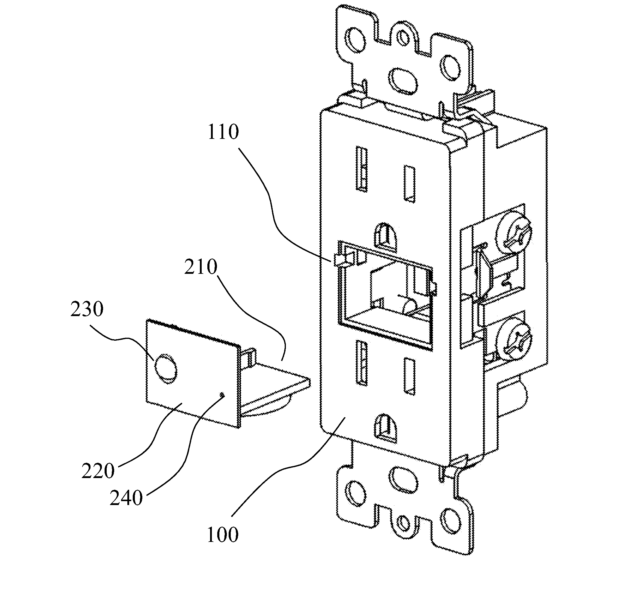
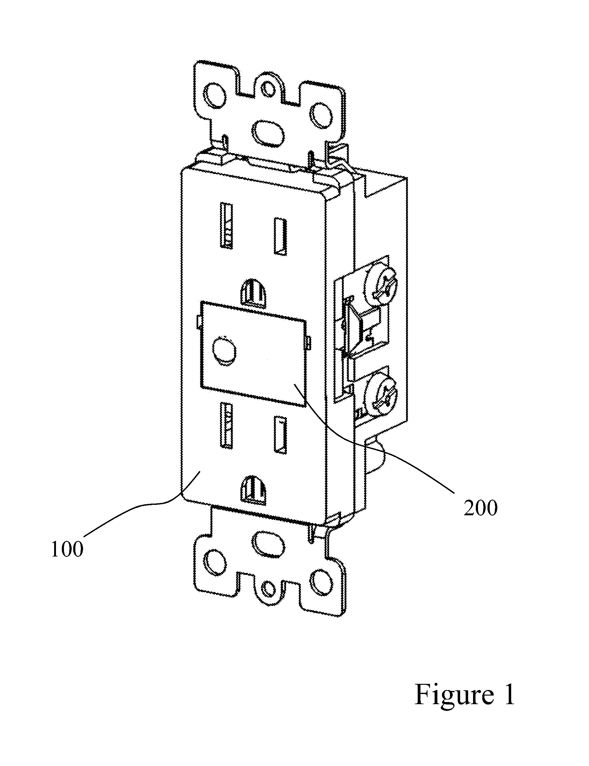
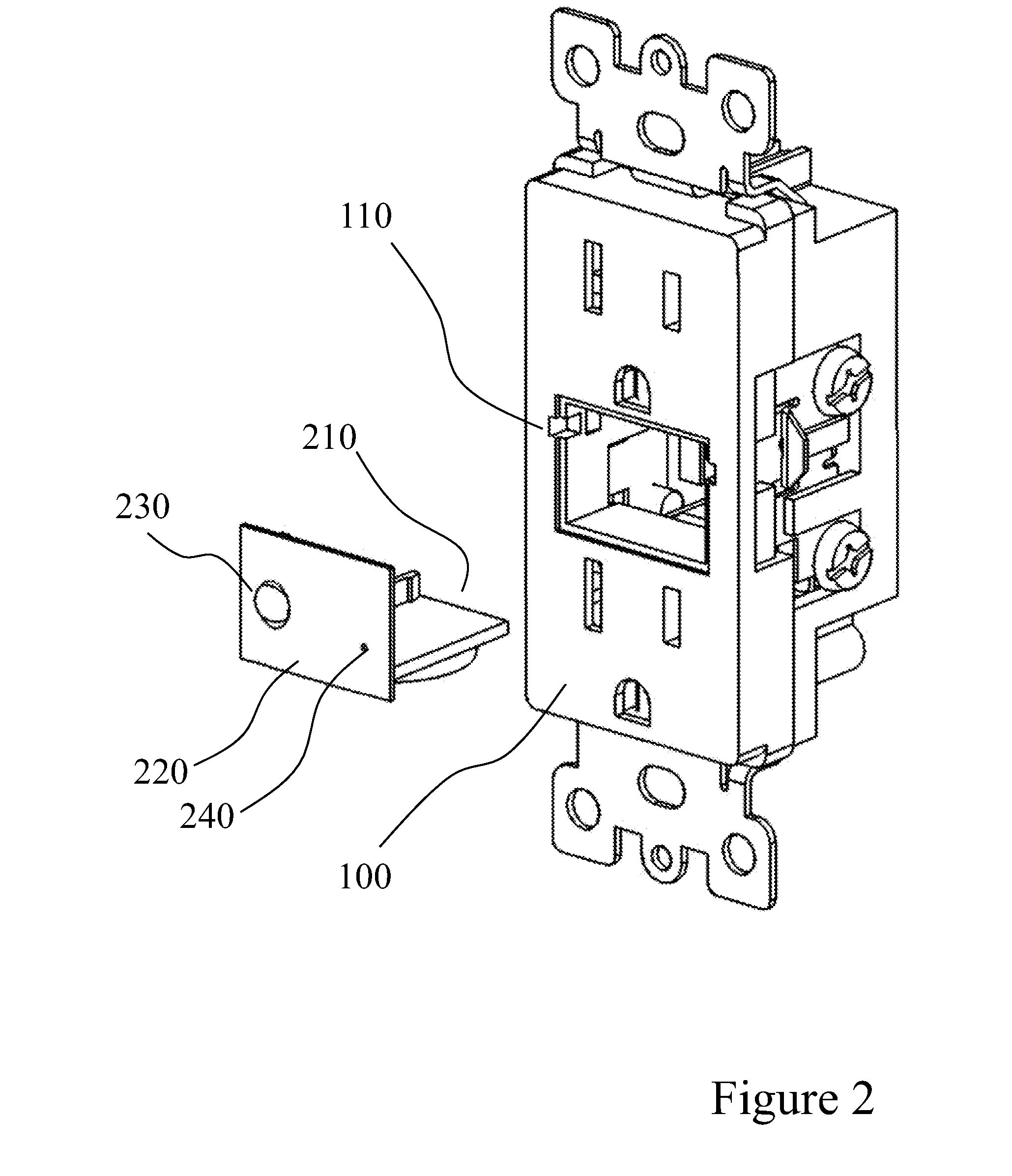
[0033]The present invention is directed to a configurable receptacle, which can be configured with a variety of function specific inserts such as safety lights and motion detectors.

[0034]Reference is made below to specific elements, numbered in accordance with the attached figures. The discussion below should be taken to be exemplary in nature, and not as limiting of the scope of the present invention. The scope of the present invention is defined in the claims, and should not be considered as limited by the implementation details described below, which as one skilled in the art will appreciate, can be modified by replacing elements with equivalent functional elements.

[0035]Systems of the present invention provide a mechanism for making use of standard building wiring to provide additional functionality including emergency lighting. In one embodiment of the present invention, a modification to the design of an electrical receptacle is provided. This redesign allows for an insert to ...


PUM


Abstract

An electrical receptacle provide outlets and a cavity for receiving an insert. The insert connects to the electrical main through the receptacle and can provide additional functionality through the insert including emergency lighting, night lighting, gas detectors and charging connections.

Description

CROSS REFERENCE TO RELATED APPLICATIONS[0001]This application claims the benefit of U.S. Provisional Application No. 60 / 847,185 filed Sep. 26, 2006 entitled “Configurable Safety Light Receptacle” and U.S. patent application Ser. No. 11 / 848,615 filed Aug. 31, 2007 entitled “Configurable Safety Light Receptacle”, each of which are incorporated herein by reference.FIELD OF THE INVENTION[0002]This invention relates generally to electrical wall receptacles. In particular, this invention relates to replacement wall receptacles that can house specific function inserts having common mechanical and electrical interfacesBACKGROUND OF THE INVENTION[0003]In most conventional buildings, both residential and commercial, electrical receptacles are spaced out on walls at fixed intervals. This allows for convenient distribution of power, but does not typically provide any additional functionality. Each receptacle typically provides two outlets. The style of the provided outlet is usually determined ...

Claims


Application Information

Patent Timeline
Patent Type & Authority Applications(United States)
IPC IPC(8): H01R27/02F21S9/02
CPCH01R27/02F21S9/022F21V21/002H02J9/02F21Y2101/02H01R13/717H01R25/006F21V21/04F21Y2115/10H05K5/0017
Inventor MISENER, DONALD LOWELL
Owner SWIDGET CORP
Why Eureka
Try Eureka