Cervical Collar Spinal Height Adjustment System

Active Publication Date: 2013-10-03
FIJI MFG LLC
10 Cites 9 Cited by

AI-Extracted Technical Summary

Problems solved by technology

Neck problems are very common amongst humans due to a wide range of causes, including anything from poor posture to arthritis to broken bones.
Neck braces can be essential to alleviate existing pain and prevent further injury, but are often too uncomfortable or immobilizing to wear for long periods of time.
Moreover, many neck braces incorporate a one-size-fits-all model that is not tailored to the needs of individual wearers.
Unfortunately, Dellanno fails to provide for sufficient support of the occipital region of...

Method used

[0032]It is contemplated that rear brace 100 could be coupled to a front brace via a fastener of the front brace that is complementary to a rear brace's fastener. For example, a fastener complementary to a hook fastener can comprise a loop fastener. In this manner, the front brace (or other component) can be removably coupled to the rear brace 100 for increased modularity.
[0042]FIG. 4 shows a rear brace 400 having a junction support receiver 450 configured to receive a modular component to expand the functionality of the brace to suit a wearer's needs. In some embodiments, one or more junction support receivers can be located on any portion of any component of a neck brace. Rear brace 400 has a rear panel 430 and an adjustment mechanism comprising an upper component 421 and a lower component 423. Rear panel 430 is partially exposed via an opening in upper component 421 and lower component 423. The exposed portion of rear panel 430 includes junction support receiver 450, which allows for receipt of a modular component as shown in FIG. 5.
[0049]Locking member 625 can comprise a movable protrusion (not shown) that is configured to move in and out of notches 635. This allows for preventing height adjustment when it is not desired. To adjust the vertical position of both occipital lobe supports 610 and 615, a ...

Benefits of technology

[0014]The neck brace can advantageously include one or more junction supports (e.g., cassettes, etc.), which can be configured to couple with a front or rear brace (or any other component) of the neck brace. In some embodiments, a junction support can be configured to couple with a junction support receiver of a rear panel. Such junction supports can comprise or couple with any suitable accessory, including for example, a belt, a back support, a strut, a ch...

Abstract

Neck braces having versatile rear braces are provided. Some rear braces comprise various components including a rear panel having notches, a height adjustment mechanism, and at least one occipital lobe support. Each component can be movably attached to another component via a fastener (e.g., ball snap, snap connector, etc.), thereby allowing one component to rotate, tilt or otherwise move in relation to the other component.

Application Domain

Fracture

Technology Topic

FastenerCervical collar +2

Image

  • Cervical Collar Spinal Height Adjustment System
  • Cervical Collar Spinal Height Adjustment System
  • Cervical Collar Spinal Height Adjustment System

Examples

  • Experimental program(1)

Example

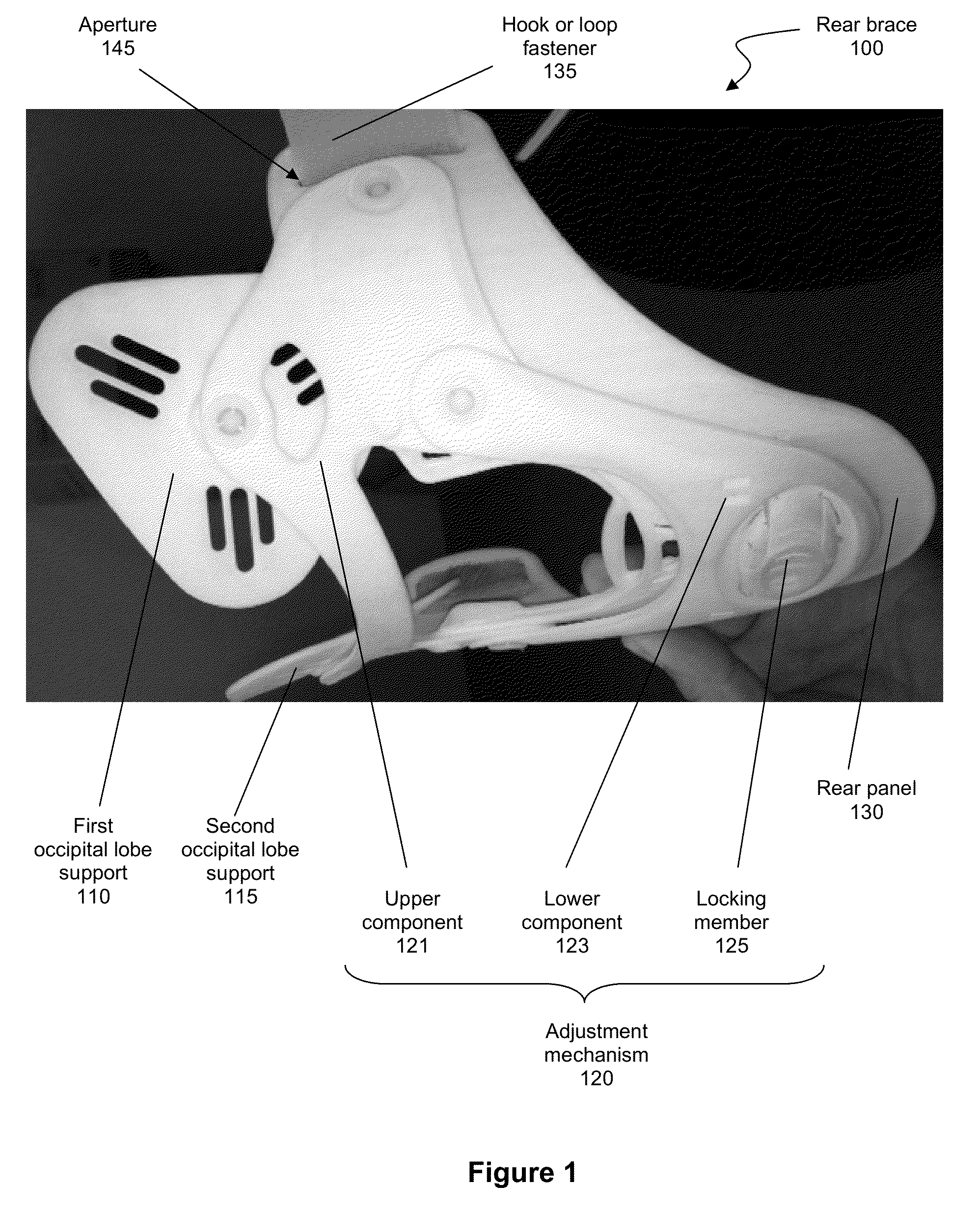
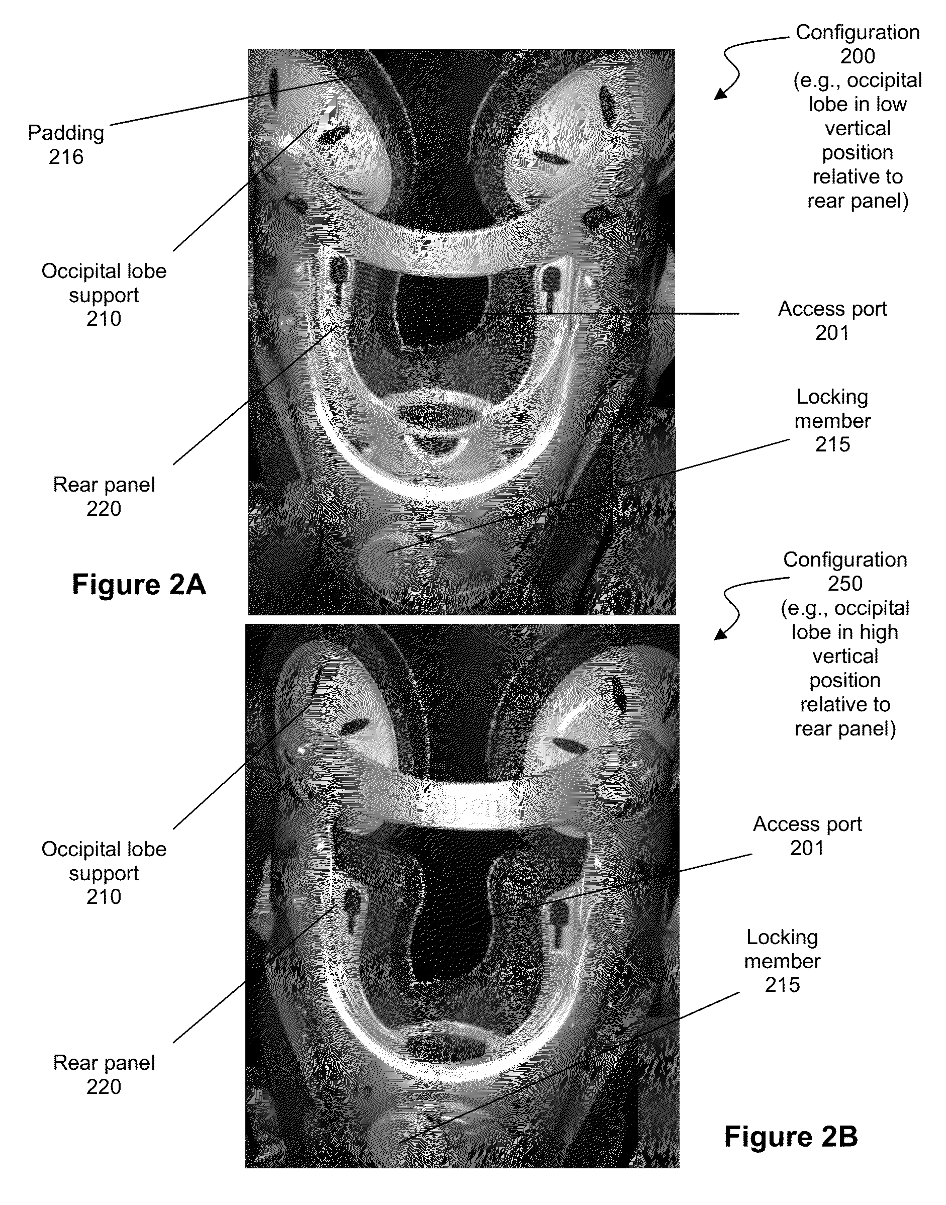
[0028]One should appreciate that the disclosed techniques provide many advantageous technical effects including providing a wearer with one or more support mechanisms to support the back of the wearer's head, and in some embodiments are configured to rotate and flex to contour to the shape of the wearer's head and thereby support the wearer's head without any areas of undue pressure. One should also appreciate that the disclosed techniques provide a wearer with a versatile brace having a user friendly height adjustment mechanism.
[0029]The following discussion provides many example embodiments of the inventive subject matter. Although each embodiment represents a single combination of inventive elements, the inventive subject matter is considered to include all possible combinations of the disclosed elements. Thus if one embodiment comprises elements A, B, and C, and a second embodiment comprises elements B and D, then the inventive subject matter is also considered to include other remaining combinations of A, B, C, or D, even if not explicitly disclosed.
[0030]FIG. 1 illustrates one embodiment of a rear brace 100 of the inventive subject matter. Rear brace 100 comprises first and second occipital lobe supports, 110 and 115, respectively, a rear panel 130, and an adjustment mechanism 120. Although two separate lobe supports are shown, it is contemplated that the rear brace could include a single lobe support configured to support both occipital lobes of a user. Adjustment mechanism 120 comprises an upper component 121 that is movably (e.g., rotatably, pivotally, etc.) coupled with lower component 123. Lower component 125 comprises a locking member 125 having a movable protrusion (not shown) configured to slidably fit at least partially within notches (not shown) of rear panel 130. In this manner, unintentional adjustment of the brace can advantageously be quickly and easily prevented. Locking members of the inventive subject matter are further described below with reference to FIGS. 7A-7C.
[0031]Rear brace 100 further comprises a hook or loop fastener 135 that can be removably attached to (e.g., threaded through aperture 145 of) rear panel 130. It is also contemplated that a fastener can be fixedly attached to real panel 130. The rear brace's fastener could attach to any rear brace component (e.g., rear panel, attachment mechanism, lobe support, etc.) in any suitable manner. Suitable manners for attaching a fastener to a rear brace component includes, for example, the use of a zipper, an adhesive, threading through an aperture, a button, sewing onto the component, or stapling onto the component. Contemplated fasteners include, among other things, hook or loop, a button, a portion of a zipper, or any other fastener suitable for coupling a rear brace with another brace.
[0032]It is contemplated that rear brace 100 could be coupled to a front brace via a fastener of the front brace that is complementary to a rear brace's fastener. For example, a fastener complementary to a hook fastener can comprise a loop fastener. In this manner, the front brace (or other component) can be removably coupled to the rear brace 100 for increased modularity.
[0033]FIGS. 2A-2B show another embodiment of a rear brace of the inventive subject matter having two different configurations achieved via an adjustment mechanism of the brace. Configuration 200 shows occipital lobe support 210 in a low vertical position relative to rear panel 220. In this configuration, a sliding protrusion of locking member 215 is aligned vertically with the bottom-most notch of rear panel 220. Configuration 250 shows occipital lobe support 210 in a higher vertical position relative to rear panel 220, as evidenced by the differences in areas of access port 201 between configuration 200 and configuration 250. In configuration 250, the sliding protrusion of locking member 215 is aligned vertically with the upper-most notch of rear panel 220.
[0034]It is contemplated that a user can modify a vertical position of an occipital lobe support relative to a rear panel quickly and easily using the inventive subject matter. This can be true even where the user is a person wearing a brace of the inventive subject matter. For example a user can, in some embodiments, unlock a locking member and adjust a position of a sliding protrusion simply by utilizing the user's thumb or finger.
[0035]The brace can further include an access port (e.g., port 201) that advantageously allows a non-wearer of the neck brace to access a posterior portion of a neck of the wearer without requiring removal or movement of the brace. For example, through the access port, a doctor could access a surgical site along the spine. In addition, the access port could be left open to allow air-flow to cool the wearer, or could be utilized as a coupling port for another device or component, including, for example, a back attachment that couples to a lumbar support and a kyphosis support such as the one described in U.S. Patent Application Publication No. 2010/0268139.
[0036]The modular nature of the braces described herein of the inventive subject matter advantageously allows a user to add to, remove from, or otherwise modify a brace's functionality to adapt to a user's specific needs. For example, where a user desires improved occipital and lumbar support, a lumbar supporting member can be coupled to a coupling port of the brace's rear panel. Where a user desires kyphosis adjustment and a chin support, a simple rear panel (e.g., one having occipital lobe support removed, etc.) can couple with a front panel having a chin support, and also comprise a kyphosis supporting or adjusting member coupled with the coupling port.
[0037]FIG. 3 shows an embodiment of an occipital lobe support 310 of rear brace 300. Occipital lobe support 310 comprises a receiver 350 that is configured to accept a protrusion 340 of adjustment mechanism 320. Protrusion 340 is rounded (e.g., spherical or egg shaped) and allows occipital lobe support 310 to rotate or pivot about protrusion 340 in all or substantially all directions. In some embodiments, an occipital lobe support can be fixedly attached to a portion of the rear brace.
[0038]It is contemplated that a rear brace of the inventive subject matter can comprise one or more occipital lobe supports that is sized and dimensioned to provide support to a wearer's occipital lobe. It is also contemplated that a rear brace of the inventive subject matter can comprise two or more occipital lobe supports that are each sized and dimensioned to provide support to a portion of a wearer's occipital lobe. Further, a rear brace can additionally or alternatively comprise one or more supports sized and dimensioned to support a temporal or parietal lobe of a wearer.
[0039]Lobe support 310 can be restricted by one or more rotation limiters, for example, a surface of adjustment mechanism 320 (or other component), or a protrusion of a component. Some rotation limiters can be configured to limit the rotation of at least one lobe support to no more than 90 degrees, 45 degrees, 20 degrees, 15 degrees, or even 10 or less degrees, or to limit a tilt of at least one lobe support to no more than 90 degrees, 45 degrees, 20 degrees, 15 degrees, or even 10 or less degrees. Of course, the specific limit of rotation could depend on various factors including the wearer, the size of the brace, and so forth.
[0040]Occipital lobe supports of all suitable shapes and sizes can be provided, including for example, a circular rounded disc, a circular flat disc, a triangular rounded disc, a triangular flat disc, a rectangular rounded disc, a rectangular flat disc, or any other suitable lobe support shape.
[0041]It is contemplated that each occipital lobe support can be movably (or fixedly) coupled to any portion of rear brace 300 in any suitable manner. For example, a portion of the rear brace 300 can comprise an aperture configured to accept a protrusion (e.g., a spherical protrusion, a mushroom shaped protrusion, an egg shaped protrusion, etc.) of an occipital lobe support.
[0042]FIG. 4 shows a rear brace 400 having a junction support receiver 450 configured to receive a modular component to expand the functionality of the brace to suit a wearer's needs. In some embodiments, one or more junction support receivers can be located on any portion of any component of a neck brace. Rear brace 400 has a rear panel 430 and an adjustment mechanism comprising an upper component 421 and a lower component 423. Rear panel 430 is partially exposed via an opening in upper component 421 and lower component 423. The exposed portion of rear panel 430 includes junction support receiver 450, which allows for receipt of a modular component as shown in FIG. 5.
[0043]FIG. 5 is a perspective view of one embodiment of a rear brace 500 coupled to junction support 520. Rear brace 500 comprises a junction support receiver 530, which is sized and dimensioned to couple with junction support coupler 525 of junction support 520. It is contemplated that the junction support coupler 525 and junction support receiver 530 can couple with one another in any suitable manner, including for example, via a snap fit (e.g., cantilever snap fit, torsional snap fit, annular snap fit, etc.), twist fit, press fit, threading a strap through an aperture, carabiner, button, hook and loop fastener, magnet, clip, or any combination thereof.
[0044]One or more accessories, such as a belt, back support, strut, chest supporting structure, lumbar supporting member, chest supporting structure, realigner, or other modular component can be coupled with junction support 520 to allow a user to customize rear brace 500 to adapt to the needs of an individual wearer. For example, a junction support can be used to couple the brace with a strut to make a cervical-thoracic brace. As another example, a junction support could be used to couple the brace with a realigner to encourage realignment of the wearer's cervical curve, thoracic curve, lumbar curve of sacral curve. One possible realigner comprises a kyphosis adjustment mechanism as described in U.S. Patent Publication No. US 2010/0268139 to Garth.
[0045]In some embodiments, it is contemplated that an accessory itself can comprise couplers that are configured to couple with junction support receiver 530. In such embodiments, a junction support 520 would not be required.
[0046]It is also contemplated that a kit can be provided comprising junction support 520 and multiple accessories, each of which could be removably coupled with junction support 520. Such a kit could allow users to modify a neck brace of the inventive subject matter to best suit an individual wearer's unique preferences without purchasing an entirely new brace.
[0047]FIGS. 6A-6B are perspective views of another embodiment of the inventive subject matter. FIG. 6A is a perspective view of a back side of the rear brace (the side facing the wearer), and FIG. 6B shows a perspective view of a front side of the rear brace (the side facing away from the wearer). The brace comprises an upper component 621, lower component 623 and locking member 625, which collectively comprise adjustment mechanism 620. The brace further comprises first occipital lobe support 610 and second occipital lobe support 615, which are movably coupled with upper component 621. As described above, a brace of the inventive subject matter could alternatively comprise a single occipital lobe support.
[0048]Each of (1) the upper component and lower component, (2) occipital lobe support and upper component, and (3) upper component and rear panel can be movably coupled via ball snaps 640 and 641 or snap connectors 642-645. Ball snap 640 removably attaches second occipital lobe support 615 to upper component 621 in a manner that allows second occipital lobe support 615 to pivot or rotate about ball snap 640, relative to upper component 621 (e.g., in directions A, B, or C, etc.). As used herein, the term “ball snap” includes a fastener comprising a ball attached to one component of a neck brace, and a receiver counterpart on a different component that is configured to grab the ball and hold it until the components are pulled apart. Ball snap 641 removably attaches first occipital lobe support 610 to upper component 621 in a manner that allows first occipital lobe support 610 to pivot or rotate about ball snap 641, relative to upper component 621 (e.g., in directions D, etc.). Snap connectors 642 and 643 attaches upper component 621 to rear panel 630 in a manner that allows upper component to rotate or pivot about snap connectors 642 and 643 relative to rear panel 630 (e.g., in directions E, etc.). Snap connectors 644 and 645 attach upper component 621 to lower component 623 in a manner that allows lower component 623 to rotate or pivot about snap connectors 644 and 645, relative to upper component 621 (e.g., in directions F, G, etc.). As used herein, a “snap connector” includes a fastener comprising a mushroom shaped protrusion (e.g., a cap and a stem) attached to one component of a neck brace, and a receiver counterpart on a different component that is configured to snap fit with a cap portion of the protrusion, thereby attaching the two components to one another. It is contemplated that each of a ball snap and a snap connector can allow a permanent or removable attachment of two or more components of a neck brace.
[0049]Locking member 625 can comprise a movable protrusion (not shown) that is configured to move in and out of notches 635. This allows for preventing height adjustment when it is not desired. To adjust the vertical position of both occipital lobe supports 610 and 615, a user can simply and easily move the protrusion from a first notch to a second notch. Thus, for example, when the protrusion is moved out of the lowest notch and placed in one of the upper notches, lower component 623 or upper component 621 will move (e.g., pivot) relative to one another, and a vertical position of occipital lobe supports 615 and 610 can be adjusted (e.g., with a single movement of the protrusion, etc.) relative to rear panel 630. It is contemplated that once the protrusion slides into one of notches 635, it can be locking in place via locking member 625. This can be achieved via any commercially suitable mechanisms, including for example, a fastening (e.g., snap fitting, etc.) of locking member 625 with a locking member acceptor (such as locking member acceptor 726 shown in FIGS. 7A-7B).
[0050]In some embodiments, the locking member (or other portion of an adjustment mechanism) can comprise a pinion having protrusions and one or more racks having notches, each notch sized and dimensioned to receive at least a portion of a pinion protrusion. One example of such a rack and pinion adjustment mechanism is described in U.S. Pat. No. 7,674,234 to Calco. It should be noted that in some embodiments, a movement of a protrusion from one notch to another notch can cause simultaneous adjustment of a vertical position of one or more occipital lobe supports.
[0051]FIGS. 7A-7B show a locking member 725 and locking member acceptor 726. Locking member 725 comprises ridge 725A, which is configured to snap fit or otherwise mate with locking member acceptor 726 to lock the position of a protrusion within a notch. FIG. 7A shows a locking member that is in an unlocked position, while FIG. 7B shows locking member in a locked position, with locking member 725 snap fit with locking member acceptor 726.
[0052]Locking members of the inventive subject matter can alternatively comprise, for example, a spring biasing mechanism such that locking member is biased towards a locked position. In such embodiments, locking member can be moved away from its biased locked position in a first notch, be moved upwards or downwards, and then released back to its biased locked position in a different notch. Moreover, a locking member can comprise a protrusion having a hook (or other bent) shape configured to move in and out of two or more notches having a divot-shaped portion. In such embodiments, a locking member can be used to lift up the protrusion out of the divot-shaped portion, and then move the protrusion from one notch to another notch having a divot-shaped portion. In this manner, the hook shaped portion and the divot-shaped portion could act as a locking mechanism.
[0053]FIGS. 8A-8B show a rear panel of the inventive subject matter interacting with a slidable protrusion of a locking member. Protrusion 899 composes a locking mechanism and is configured to slide in and out of first notch 896, second notch 897, and third notch 898. It is contemplated that slidable protrusion and notches 896-898 can allow a user of a neck brace of the inventive subject matter to quickly and easily adjust a vertical position of one or more occipital lobe supports with a single adjustment.
[0054]Rear panel 830 can further include guiding mechanism 890 to stabilize a movement of a lower component (or other component) relative to the rear panel. An adjustment mechanism of a brace can comprise a prominence that is configured to slide along guiding mechanism 890 in directions Z. This guiding mechanism 890 can keep an adjustment mechanism from moving side to side in directions Y. In some other embodiments, a guiding mechanism can keep an adjustment mechanism from unintentionally moving in an up or down direction, diagonal direction, or any other possible direction.
[0055]It is contemplated that a neck brace of the inventive subject matter can comprise 1, 2, 5, 10, or even 20 or more components. It is also contemplated that each component can be of any suitable shape and size. For example, a rear brace can be sized and dimensioned to wrap around an entire neck of a wearer. As another example, a rear brace can be sized and dimensioned to wrap around a neck, chin, and trapezius muscle of a wearer. As yet another example, a front brace can be configured to wrap around a chest, neck and lower back of a wearer.
[0056]Each component can be made of any suitable material(s), including for example, a foam, a gel, a silicon, a plastic, a cotton, a Nylon, or any other suitable material. Thus, it is contemplated that a rear brace can be made entirely of plastic(s), while a padding that removably attaches to an interior side of the rear brace is made entirely of cotton, foam and polyester (e.g., a cotton lining and a polyester lining sandwiching a foam layer.
[0057]As used in the description herein and throughout the claims that follow, the meaning of “a,”“an,” and “the” includes plural reference unless the context clearly dictates otherwise. Also, as used in the description herein, the meaning of “in” includes “in” and “on” unless the context clearly dictates otherwise.
[0058]The recitation of ranges of values herein is merely intended to serve as a shorthand method of referring individually to each separate value falling within the range. Unless otherwise indicated herein, each individual value is incorporated into the specification as if it were individually recited herein. All methods described herein can be performed in any suitable order unless otherwise indicated herein or otherwise clearly contradicted by context. The use of any and all examples, or exemplary language (e.g. “such as”) provided with respect to certain embodiments herein is intended merely to better illuminate the invention and does not pose a limitation on the scope of the invention otherwise claimed. No language in the specification should be construed as indicating any non-claimed element essential to the practice of the invention.
[0059]Groupings of alternative elements or embodiments of the invention disclosed herein are not to be construed as limitations. Each group member can be referred to and claimed individually or in any combination with other members of the group or other elements found herein. One or more members of a group can be included in, or deleted from, a group for reasons of convenience and/or patentability. When any such inclusion or deletion occurs, the specification is herein deemed to contain the group as modified thus fulfilling the written description of all Markush groups used in the appended claims.
[0060]As used herein, and unless the context dictates otherwise, the term “coupled to” is intended to include both direct coupling (in which two elements that are coupled to each other contact each other) and indirect coupling (in which at least one additional element is located between the two elements). Therefore, the terms “coupled to” and “coupled with” are used synonymously.
[0061]It should be apparent to those skilled in the art that many more modifications besides those already described are possible without departing from the inventive concepts herein. The inventive subject matter, therefore, is not to be restricted except in the scope of the appended claims. Moreover, in interpreting both the specification and the claims, all terms should be interpreted in the broadest possible manner consistent with the context. In particular, the terms “comprises” and “comprising” should be interpreted as referring to elements, components, or steps in a non-exclusive manner, indicating that the referenced elements, components, or steps may be present, or utilized, or combined with other elements, components, or steps that are not expressly referenced. Where the specification claims refers to at least one of something selected from the group consisting of A, B, C . . . and N, the text should be interpreted as requiring only one element from the group, not A plus N, or B plus N, etc.

PUM

no PUM

Description & Claims & Application Information

We can also present the details of the Description, Claims and Application information to help users get a comprehensive understanding of the technical details of the patent, such as background art, summary of invention, brief description of drawings, description of embodiments, and other original content. On the other hand, users can also determine the specific scope of protection of the technology through the list of claims; as well as understand the changes in the life cycle of the technology with the presentation of the patent timeline. Login to view more.
Why Eureka
Try Eureka