Magnetic resonance apparatus and data acquisition method with decoupling between transmit and receive coils

a magnetic resonance and data acquisition technology, applied in the field of magnetic resonance apparatus and data acquisition method with decoupling between transmit and receive coils, can solve the problems of increasing rf power requirements, excessive heating of samples, and artifacts in images, and achieves the effects of reducing dynamic range requirements, increasing mri signal level proportionally, and more isolation

Active Publication Date: 2013-10-17
OZEN ALI CAGLAR +1
View PDF4 Cites 29 Cited by
  • Summary
  • Abstract
  • Description
  • Claims
  • Application Information

AI Technical Summary

Benefits of technology

[0010]The isolation method is useful for applications that make use of information about spin dynamics in presence of B1 excitation field and applications of zero echo time imaging. Magnetic field decoupling is achieved by manipulating amplitudes and phases of the currents that drive the transmit coils. This approach is advantageous over other methods in the sense of providing more isolation, flexibility of applied RF waveforms, and reduced dynamic range requirements. Use of transmit arrays to cancel B1 induced currents stands for an alternative decoupling method or an additional procedure to provide extra decoupling which increases MRI signal level proportionally by reducing B1 induced potential.

Problems solved by technology

However, coupling from transmit coil to the receive coil causes artifacts to occur in the image.
In continuous wave NMR, for example, concurrent transmission and reception is used and RF bridges are utilized for isolation between MRI signal and RF signal which increases RF power requirements resulting in excessive heating of the sample.
(Brunner, D. O., Pavan, M., Dietrich, B., Heller, A., Pruessmann, K. P. Sideband Excitation for Concurrent RF Transmission and Reception, In: Proceedings, 19th Annual Meeting of ISMRM, 2011) However, off resonant excitation increases RF power requirements to achieve the amount of flip angle possible with on resonant excitation.
Besides, hardware to implement sideband excitation is complex and expensive.

Method used


Image

  • Magnetic resonance apparatus and data acquisition method with decoupling between transmit and receive coils
  • Magnetic resonance apparatus and data acquisition method with decoupling between transmit and receive coils
  • Magnetic resonance apparatus and data acquisition method with decoupling between transmit and receive coils

Examples


Embodiment Construction

Decoupling

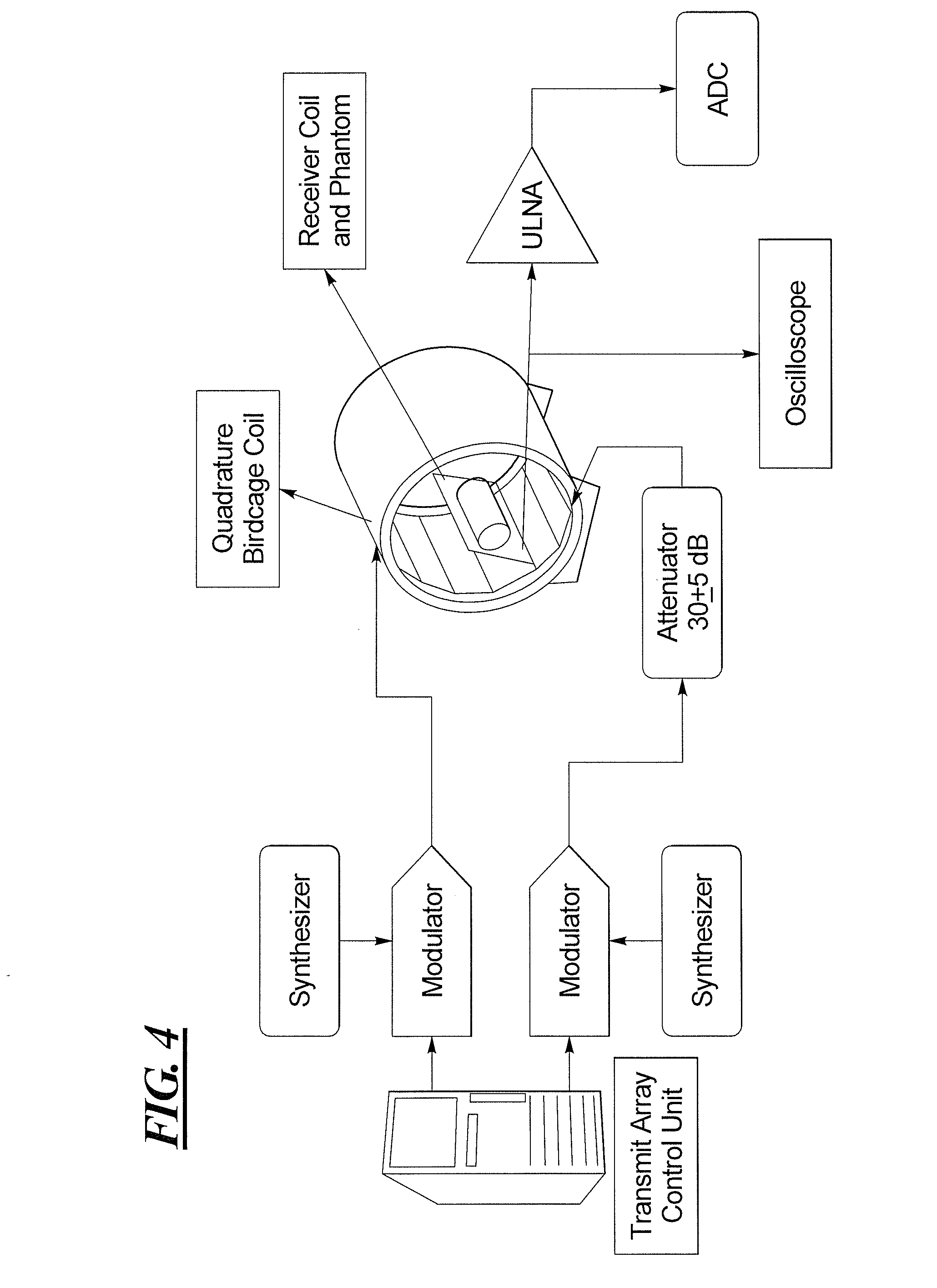
[0031]Transmit RF pulse applied from a set of transmitting coils induce a current in the receive coil which is called as B1 induced current throughout the text. Using another set of transmit coils which are called as decoupling coils, driven by a certain phase, amplitude and frequency modulation characteristics such as to cancel B1 induced current generated by the set of transmitting coils. In this section, this idea of decoupling is explained and experimental results implemented in Siemens 3T Tim Trio Tx-Array system are shown.

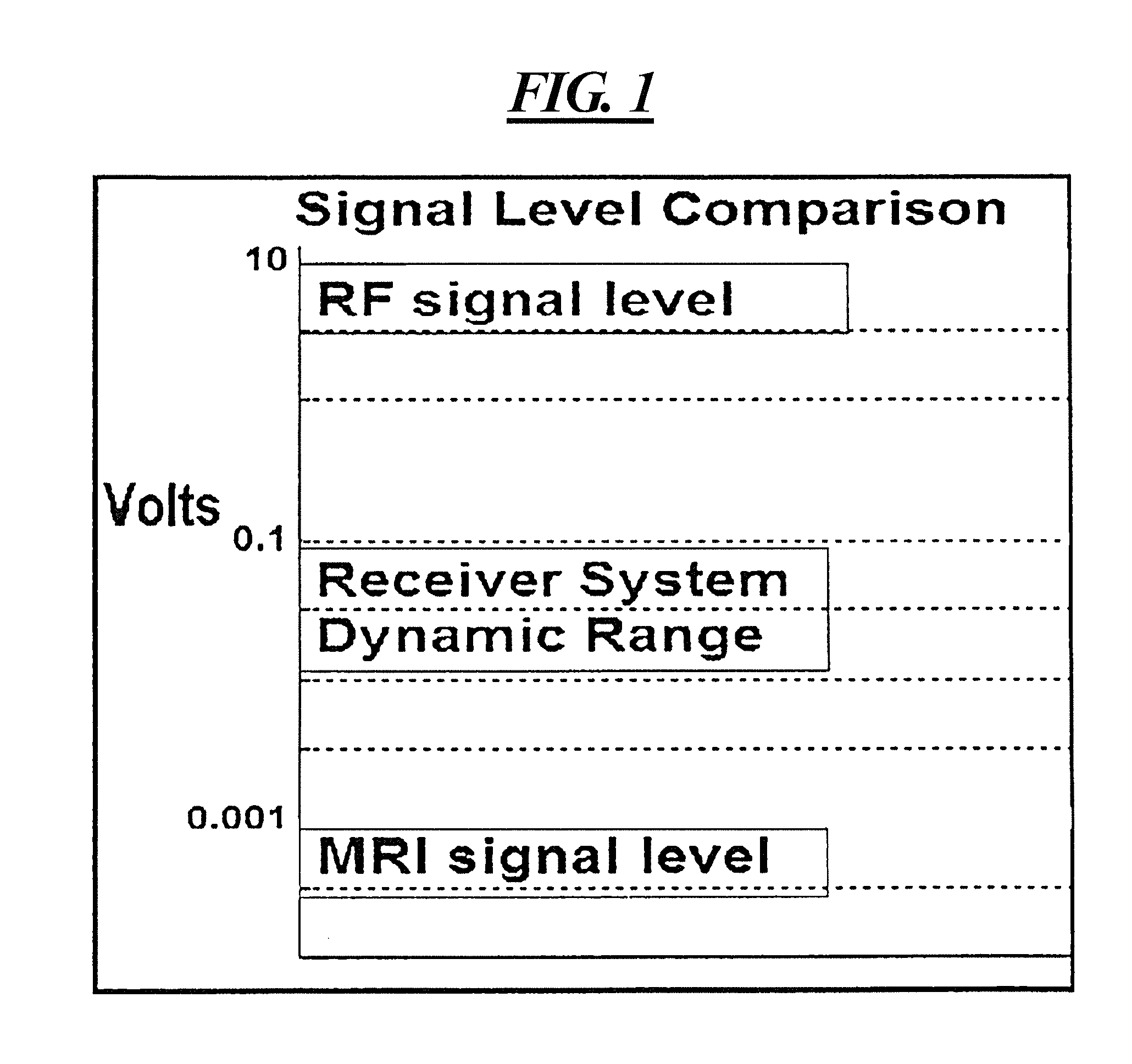
[0032]In a concurrent excitation and reception experiment, acquired signal can be considered in four parts: B1 induced voltage, MR signal induced from change of total magnetization of the excited spins, transmit noise induced voltage, and the thermal noise. The signal is analyzed in terms of the weightings of its components which are B1 induced voltage, spin magnetization induced signal, and thermal noise. MRI signal is too weak compared to RF signa...


PUM


Abstract

In magnetic resonance data acquisition, decoupling between the transmit and receive coils is achieved by using a transmit array system wherein induced currents from the transmit coils cancel each other, resulting in a total of zero current in the receive coil. Forward and reversed polarized transmit coil pairs are set to cancel the individual currents of each other, or of a receive coil. Linearly polarized fields can also be used to effect the decoupling. The decoupling allows the magnetic resonance data acquisition system to be operated for concurrent excitation of the nuclear spins and reception of the resulting magnetic resonance signals.

Description

RELATED APPLICATION[0001]The present application claims the benefit of the filing date of provisional application No. 61 / 624,473, filed on Apr. 16, 2012.BACKGROUND OF THE INVENTION[0002]1. Field of the Invention[0003]The invention is related to decoupling between transmit and receive coils using a transmit array in a magnetic resonance apparatus. It employs decoupling between RF transmit field and the magnetic field of receiver coil by reducing the total current induced in a receive coil by transmit coils. It can be used to achieve concurrent RF excitation and magnetic resonance imaging (MRI) signal reception so that magnetic resonance imaging based on the spin characteristics during excitation, and the concept of zero echo time can be realized. It can also be used in continuous wave MR spectroscopy, continuous wave MRI and MRI with ultra-short echo time (UTE), as well as real time field / impedance monitoring.[0004]2. Description of the Prior Art[0005]In MRI, both transmit and receiv...

Claims


Application Information

Patent Timeline
Patent Type & Authority Applications(United States)
IPC IPC(8): G01R33/54
CPCG01R33/543G01R33/3657G01R33/4816G01R33/4824G01R33/5612
Inventor OZEN, ALI CAGLARATALAR, ERGIN
Owner OZEN ALI CAGLAR
Why Eureka
Try Eureka