Video And Content Controlled Backlight

a backlight and video technology, applied in the field of video and content controlled backlight, can solve the problems of difficult to switch on or off based on the image, slow turning on or off, fractional backlighting, etc., and achieve the effect of enabling image contrast separation and image contras

Active Publication Date: 2013-10-24
LITTELFUSE INC
View PDF3 Cites 0 Cited by
  • Summary
  • Abstract
  • Description
  • Claims
  • Application Information

AI Technical Summary

Benefits of technology

The present invention is about improving display devices, such as LCDs, that use light emitting diodes (LEDs). Current LCD panels commonly use a technology called CCFL, which allows for only overall brightness control. However, this invention proposes the use of LEDs in the display devices. This leads to better image quality and separation of brightness and color. The invention also utilizes the LEDs as off-on light shutters to control each pixel, resulting in an increased number of pixels controlled. By adjusting the LED current, the brightness can be adjusted, and energy efficiency is improved. Overall, this technology improves the resolution, brightness, and energy efficiency of LCD panels.

Problems solved by technology

However due to the use of hazardous materials in CCFL, the industry is phasing out CCFL from the backlight application.
Furthermore the light is slow to turn on or off, thus it is difficult to switch it on or off based on the image.
Furthermore the CCFL backlight lights the back of the whole display and has difficulty in providing zone backlighting, or fractional backlighting based on the image to be displayed.
With CCFL technology it is difficult to only light the needed area or zone, and especially at video image rate (30 to 60 frames a second) sine CCFL cannot be turned on or off at fast rates.
However this solution is more costly than present CCFL backlights.
The LED backlighting is also less energy efficient than the CCFL light source.
Namely the white color is not truly optically white thus the resultant color quality of the image is poor.

Method used


Image

  • Video And Content Controlled Backlight
  • Video And Content Controlled Backlight
  • Video And Content Controlled Backlight

Examples


Embodiment Construction

[0021]The present invention relates to the use of LEDs in a display device, e.g., LCDs. In one embodiment, an array of LED modules or clusters is used as a backlight of the LCD. Each of these modules or clusters comprises a plurality of LEDs of RGB that is suitable for generating white light. In one implementation, the module or cluster comprises RGBB (an extra blue LED in the cluster), or RGBYC (which in addition to the red green and blue, has a yellow and cyan LED), or RGBXYZ, where X is an additional color LED, Y is an additional color LED and Z is an additional color LED in a cluster. Based on the specific application, or specific use of the display, either for TV, or still photography, or display of art, one can select any LED combination in a cluster. For simplicity of the explanation, without limiting it to the discussed example, the present invention is described in using RGB LED clusters.

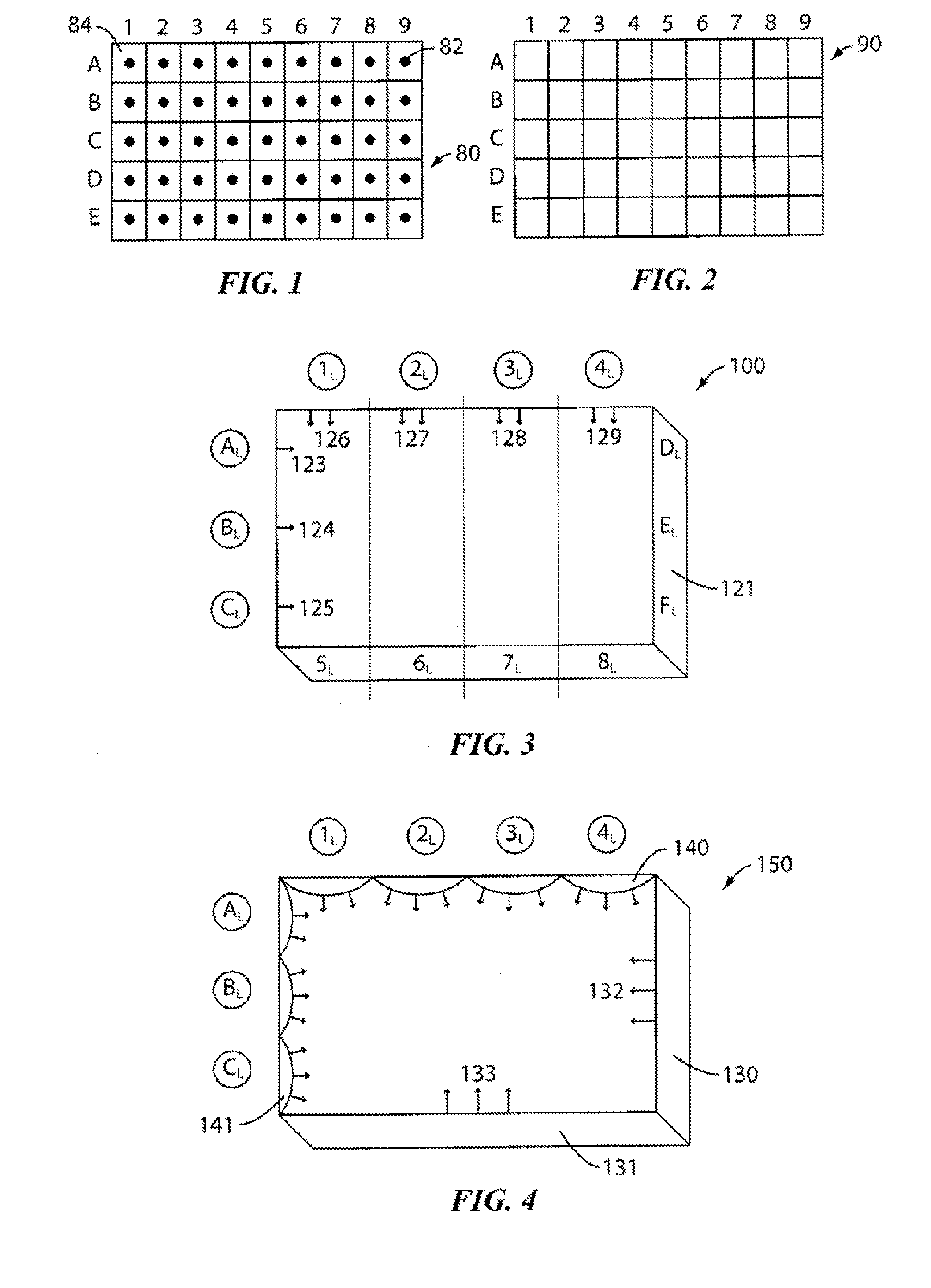
[0022]FIGS. 1 and 2 illustrate an LED based backlighting panel 80 and a liquid crystal ...


PUM


Abstract

pa A display device includes a display panel; and a backlight panel provided below the display panel and defining a plurality of regions. A first array of light emitting diodes (LEDs) is provided along a first direction, each LED of the first array being coupled to a first line. A driver is coupled to the first line to drive the LEDs coupled to the first line. A second array of LEDs is provided along a second direction, each LEDs of the second array being coupled to a second line. A lighting condition of the regions defined by the backlight panel is controlled by turning on or off the LEDs.

Description

CROSS REFERENCE TO RELATED APPLICATIONS[0001]This application is a continuation of, and claims the benefit under 35 U.S.C. §120 from, nonprovisional U.S. patent application Ser. No. 11 / 838,768, entitled “Video And Content Controlled Backlight,” filed on Aug. 14, 2007, the subject matter of which is incorporated herein by reference. U.S. patent application Ser. No. 11 / 838,768 claims the benefit under 35 U.S.C. §119 from U.S. provisional patent application Ser. No. 60 / 837,710, filed on Aug. 14, 2006, the subject matter of which is incorporated herein by reference.TECHNICAL FIELD[0002]The present invention relates to a display device and a backlight component thereof.BACKGROUND INFORMATION[0003]Liquid crystal displays (“LCDs”) contain a backlight, which is the source of light that enables the LCDs to display images and texts. The liquid crystal that is in the display acts as a shutter to let the light through or not based on the command that is delivered by a corresponding control chip...

Claims


Application Information

Patent Timeline
Patent Type & Authority Applications(United States)
IPC IPC(8): G09F13/04H05B44/00
CPCG09F13/04G09G3/3413G09G3/3426G09G2310/0232G09G2320/0238G09G2320/043G09G2320/0646G09G2320/066G09G2330/021H05B45/20H05B45/37
Inventor ZOMMER, NATHANOCHI, SAM SEIICHIRO
Owner LITTELFUSE INC
Why Eureka
Try Eureka