Method for forming a stent

Active Publication Date: 2013-10-24
MEDTRONIC VASCULAR INC
View PDF4 Cites 5 Cited by
  • Summary
  • Abstract
  • Description
  • Claims
  • Application Information

AI Technical Summary

Benefits of technology

The present invention provides a method for forming a stent by creating a wave form from a flexible material. The wave form has straight and curved sections that are connected at specific points to form a helical coil. The excess material is removed from the ends of the wave form, and the stent is smoothed. The stent formed using this method has a wave-like structure that improves its flexibility and provides better support to the blood vessels. The technical effects of this stent include improved flexibility, better support, and reduced risk of complications during angioplasty procedures.

Problems solved by technology

The small size and complexity of some stent designs generally makes its formation difficult.

Method used


Image

  • Method for forming a stent
  • Method for forming a stent
  • Method for forming a stent

Examples


Embodiment Construction

[0020]The following detailed description is merely exemplary in nature and is not intended to limit the invention or the application and use of the invention. Furthermore, there is no intention to be bound by any expressed or implied theory presented in the preceding technical field, background, brief summary or the following detailed description.

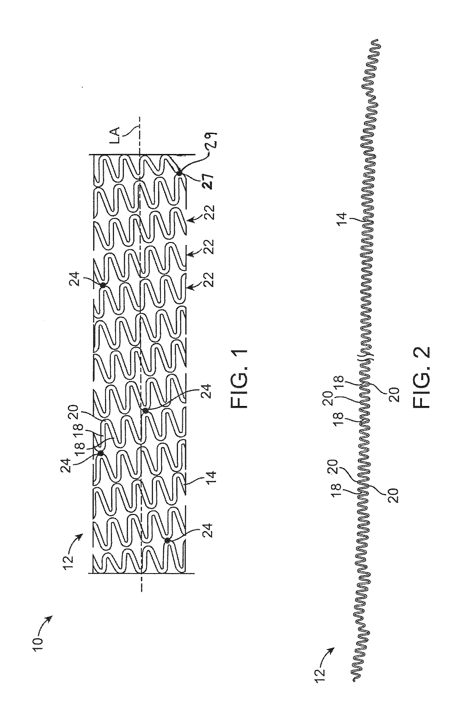
[0021]FIG. 1 schematically illustrates a stent 10 that has been manufactured according to an embodiment of the present invention. The stent 10 is generally cylindrical in shape and has a longitudinal axis extending through the center of the stent 10. The stent 10 includes a continuous wave form 12 that is formed from a formable material 14 using a suitable forming apparatus.

[0022]As illustrated in FIG. 2, the wave form 12 may be formed so that the wave form 12 includes a plurality of struts 18 and a plurality of crowns 20. Each crown 20 is a curved portion or turn within the wave form 12 that connects adjacent struts 18 to define the contin...


PUM

PropertyMeasurementUnit
Speedaaaaaaaaaa
Speedaaaaaaaaaa
Widthaaaaaaaaaa

Abstract

A method of forming a stent includes forming a wave form from a formable material. The wave form includes a plurality of substantially straight portions and a plurality of curved portions, each curved portion connecting adjacent substantially straight portions. The method includes wrapping the wave form around a mandrel at an angle to form a helical coil comprising a plurality of turns, connecting a first curved portion of a first turn to an adjacent second curved portion of a second turn at a position along the wave form to define an end of the stent, and removing excess material from an end of the wave form extending past the first curved portion while smoothing the end of the stent.

Description

BACKGROUND OF THE INVENTION[0001]1. Field of the Invention[0002]The present invention is generally related to a method for forming a stent.[0003]2. Background of the Invention[0004]A stent is typically a hollow, generally cylindrical device that is deployed in a body lumen from a radially contracted configuration into a radially expanded configuration, which allows it to contact and support a vessel wall. A plastically deformable stent can be implanted during an angioplasty procedure by using a balloon catheter bearing a compressed or “crimped” stent, which has been loaded onto the balloon. The stent radially expands as the balloon is inflated, forcing the stent into contact with the body lumen, thereby forming a support for the vessel wall. Deployment is effected after the stent has been introduced percutaneously, transported transluminally, and positioned at a desired location by means of the balloon catheter.[0005]Stents may be formed from wire(s) or strip(s) of material, may be ...

Claims


Application Information

Patent Timeline
IPC IPC(8): A61F2/88B23P13/04
CPCA61F2/88A61F2002/91558A61F2240/001B21F3/04B23K26/3576B23K26/361Y10T29/49995
Inventor BALDWIN, MATTHEWBLISS, RICHARD
Owner MEDTRONIC VASCULAR INC
Why Eureka
Try Eureka