Measuring tool

a technology of measuring tool and measuring blade, which is applied in the field of measuring tools, can solve problems such as less than optimal

Inactive Publication Date: 2013-10-31
JONES MICHAEL D
View PDF9 Cites 5 Cited by
  • Summary
  • Abstract
  • Description
  • Claims
  • Application Information

AI Technical Summary

Benefits of technology

[0014]Optionally each of the arms can fold back on itself to enable the tool to be stowed in a compact manner.

Problems solved by technology

However this can be less than optimal because it involves the use of a second tool, namely the protractor.

Method used


Image

  • Measuring tool
  • Measuring tool
  • Measuring tool

Examples


Embodiment Construction

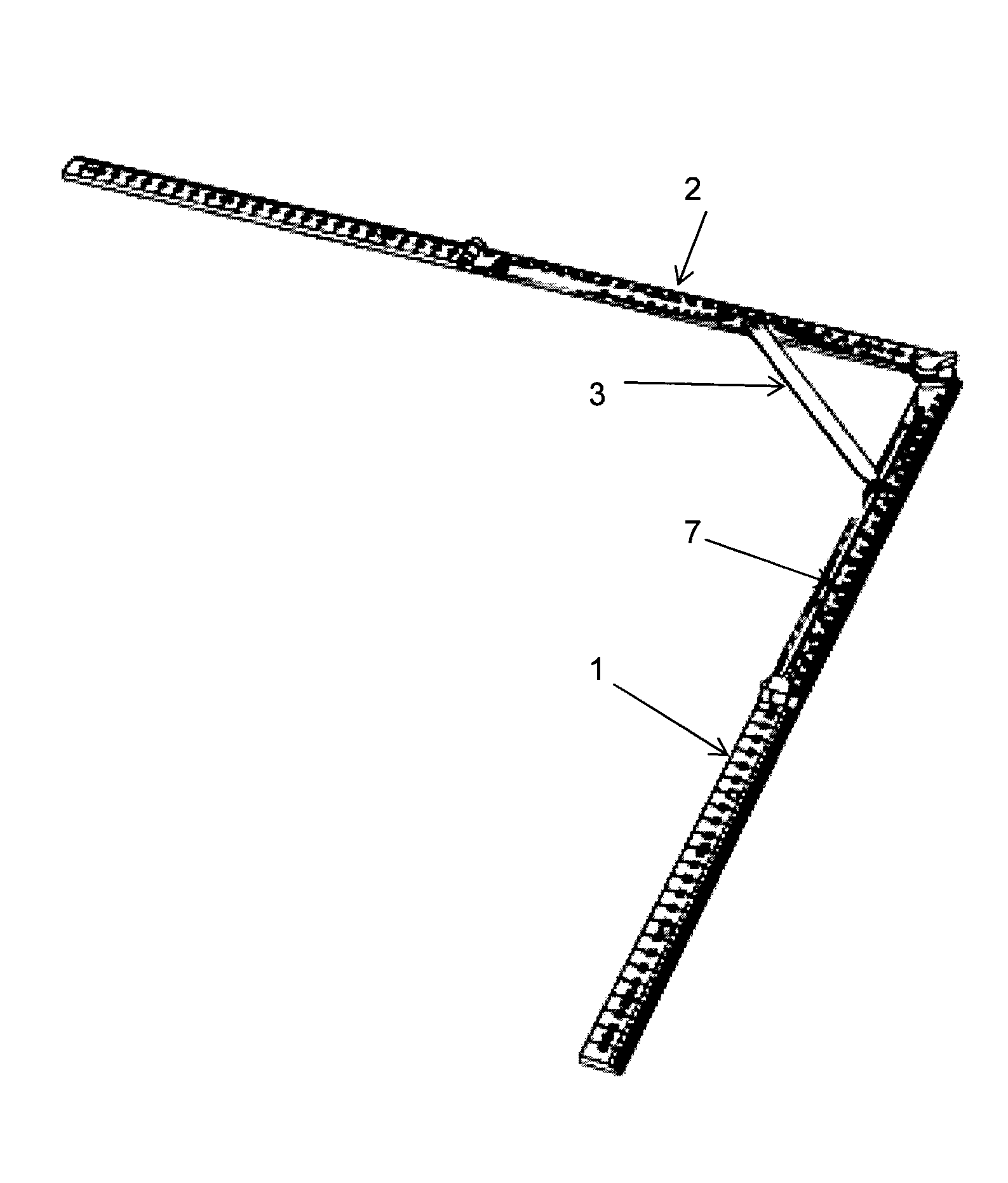
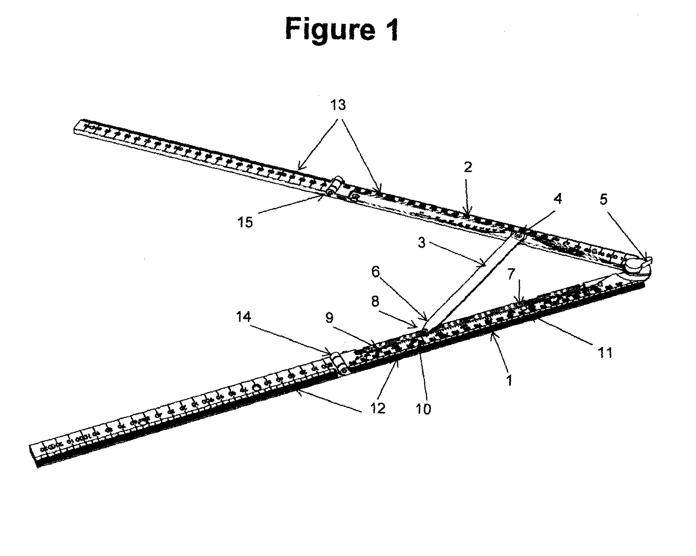
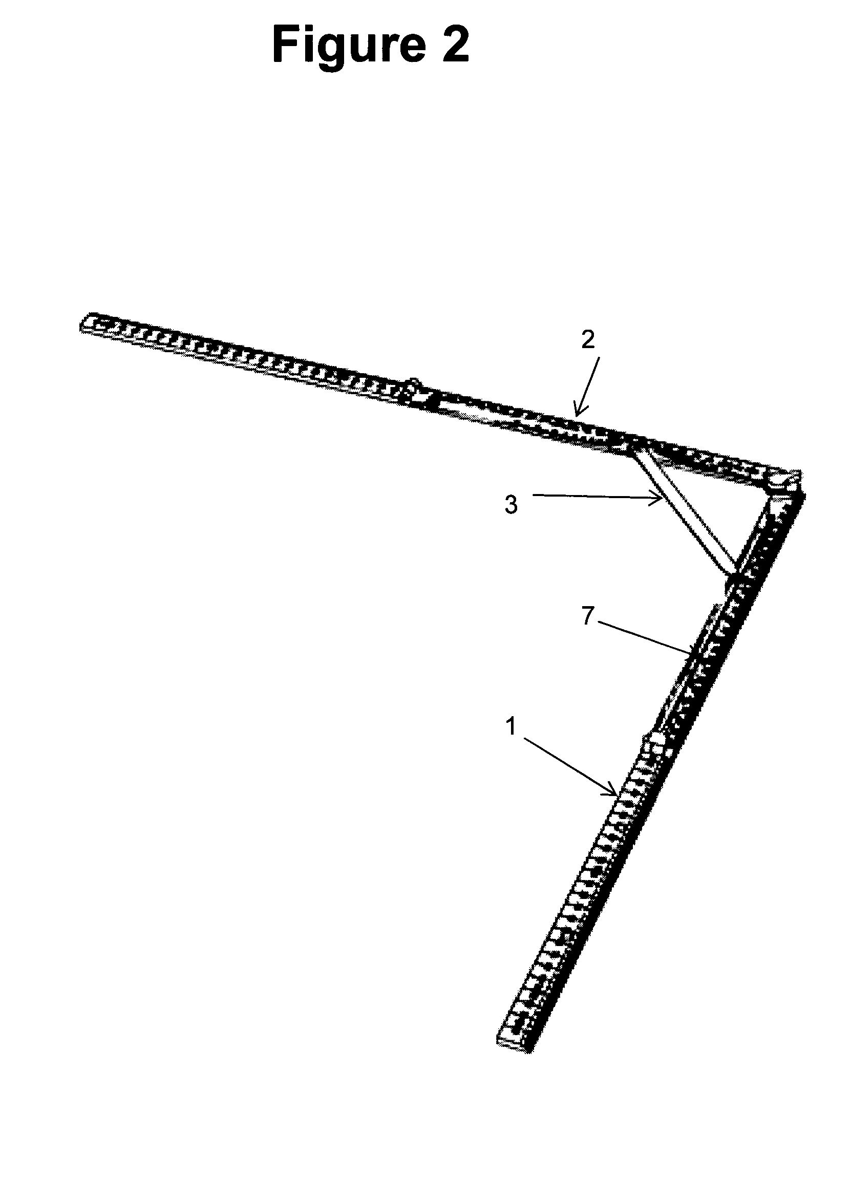
[0021]Referring to FIG. 1, the bevel tool has a first arm 1, a second arm 2 and a pointer 3. The pointer 3 is fixed to and swings about a pivot point 4 on the second arm. A locking nut 5 can be turned one way to fix the angle between the two arms, and then turned the other way enable the arms to pivot. The distill end of the pointer has an arrowhead 6 which can be swung to contact various positions along the first arm 1. The first arm has an angle scale 7 running along its inside edge. The position along the scale 7 that the pointer touches marks the angle between the two arms 1, 2 at any one time. The angle between the arms can thus be read without having to lay them against a protractor.

[0022]The arrowhead 6 of the pointer has a small mound 8 which can be pressed into a slot 9 running along the angle scale. This helps to stiffen movement of the pointer along the scale so that it cannot too easily pivot away from the scale, for example under the force of gravity, when one is readin...


PUM


Abstract

A measuring tool which has a first arm and a second arm where at least one of the arms is able to pivot so that the arms can be set at a variety of angles with respect to one another. The tool also has an angle scale and a pointer. The angle scale runs along the first arm and the pointer is able to pivot so that it can point to a variety of positions along the angle scale to give the angle between the arms, the pointer being arranged such that it can be swung away from and clear of the angle scale.

Description

CROSS-REFERENCE TO RELATED APPLICATIONS[0001]This application is the national phase under 35 U.S.C. §371 of PCT International Application No. PCT / NZ2011 / 000148, filed Aug. 2, 2011, which claims the benefit of New Zealand Patent Application No. 588226 filed Sep. 28, 2010, the entire contents of the aforementioned applications are hereby incorporated herein by reference.FIELD OF INVENTION[0002]This invention relates to a tool suitable for use in measuring angles.BACKGROUND[0003]In the field of construction it is known to use a bevel tool to measure the angle between intersecting surfaces, for example two walls which merge into one another. Some bevels have two arms which can swing about a common pivot point. The arms are opened up, one is placed against one wall and the other against another wall. The angle between the arms thus reproduces the angle between the walls. By subsequently laying the arms against a protractor the exact angle of the arms and thus the wall is measured. Howeve...

Claims


Application Information

Patent Timeline
Patent Type & Authority Applications(United States)
IPC IPC(8): G01B5/24
CPCG01B5/24G01B3/06G01B3/56
Inventor JONES, MICHAEL D.
Owner JONES MICHAEL D
Why Eureka
Try Eureka