Picture coding supporting block partitioning and block merging

a technology of partitioning and merging, which is applied in the field of picture and/or video coding, can solve the problems of increasing the amount of bits required to encode the prediction residual, limiting the freedom of subdividing a picture, and reducing the signaling overhead for signaling the merge information, so as to reduce the redundancy between partitioning coding and merging coding, the effect of increasing the coding efficiency

Active Publication Date: 2013-10-31
GE VIDEO COMPRESSION LLC
View PDF2 Cites 181 Cited by
  • Summary
  • Abstract
  • Description
  • Claims
  • Application Information

AI Technical Summary

Benefits of technology

[0012]The idea underlying the present invention is that a further coding efficiency increase may be achieved if for a current block of a picture, for which the bit stream signals one of supported partitioning patterns, a reversal of the partitioning by block merging is avoided. In particular, if the signaled one of the supported partitioning patterns specifies a subdivision of the block into two or more further blocks, a removal of certain coding parameter candidates for all further blocks, except a first further block of the further blocks in a coding order, is performed. In particular, those coding parameter candidates are removed from the set of coding parameter candidates for the respective further block, the coding parameters of which are the same as coding parameters associated with any of the further blocks which, when being merged with th

Problems solved by technology

For example, predictive codecs use a block granularity in order to achieve a good compromise between very precisely set prediction parameters set at a high spatial resolution with, however, spending too much side information for the prediction parameters on the one hand and too coarsely set prediction parameters, causing the amount of bits necessitated to encode the prediction residual to increase due to the lower spatial resolution of

Method used


Image

  • Picture coding supporting block partitioning and block merging
  • Picture coding supporting block partitioning and block merging
  • Picture coding supporting block partitioning and block merging

Examples


Embodiment Construction

[0026]With respect to the following description, it is noted that whenever the same reference sign is used in connection with different figures, the explanations with regard to the respective element presented with respect to one of these figures shall equally apply to the other figures, provided that such transferring of explanations from one figure to the other does not conflict with the remaining description of this other figure.

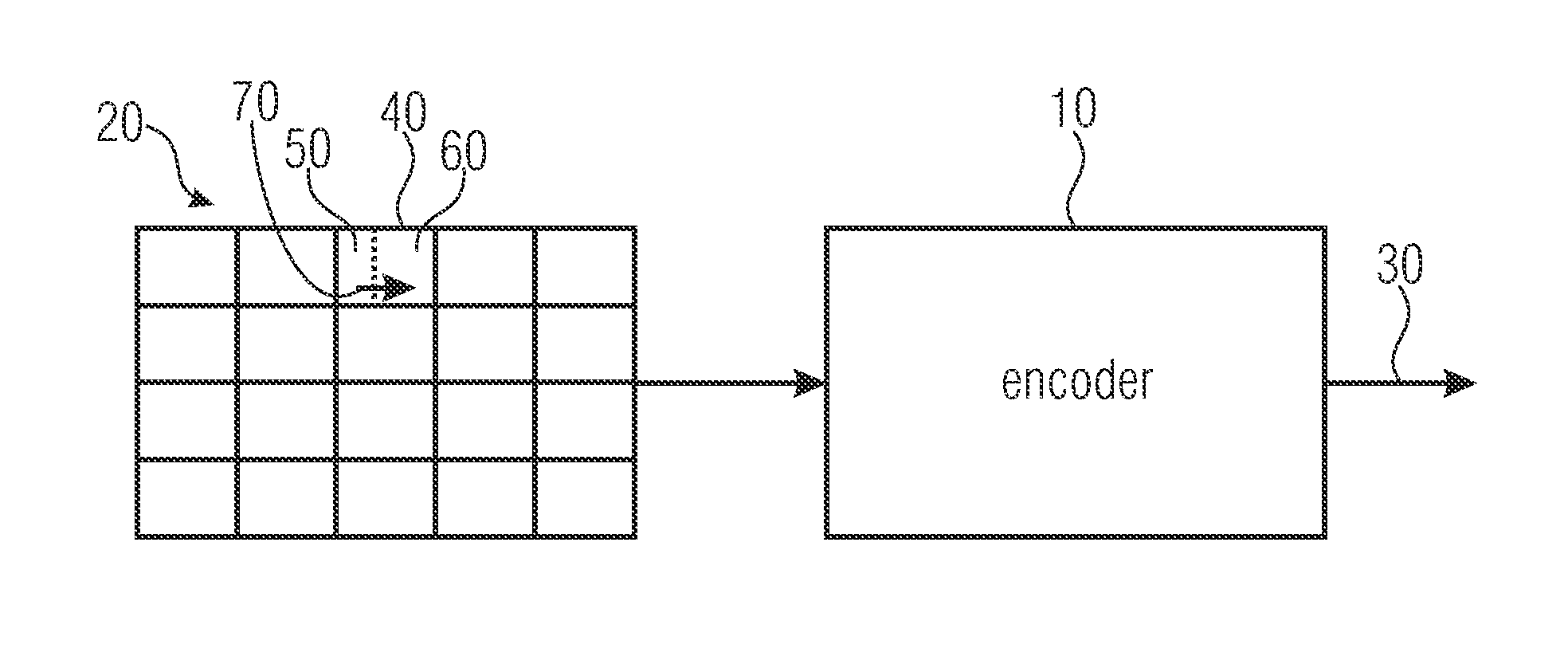
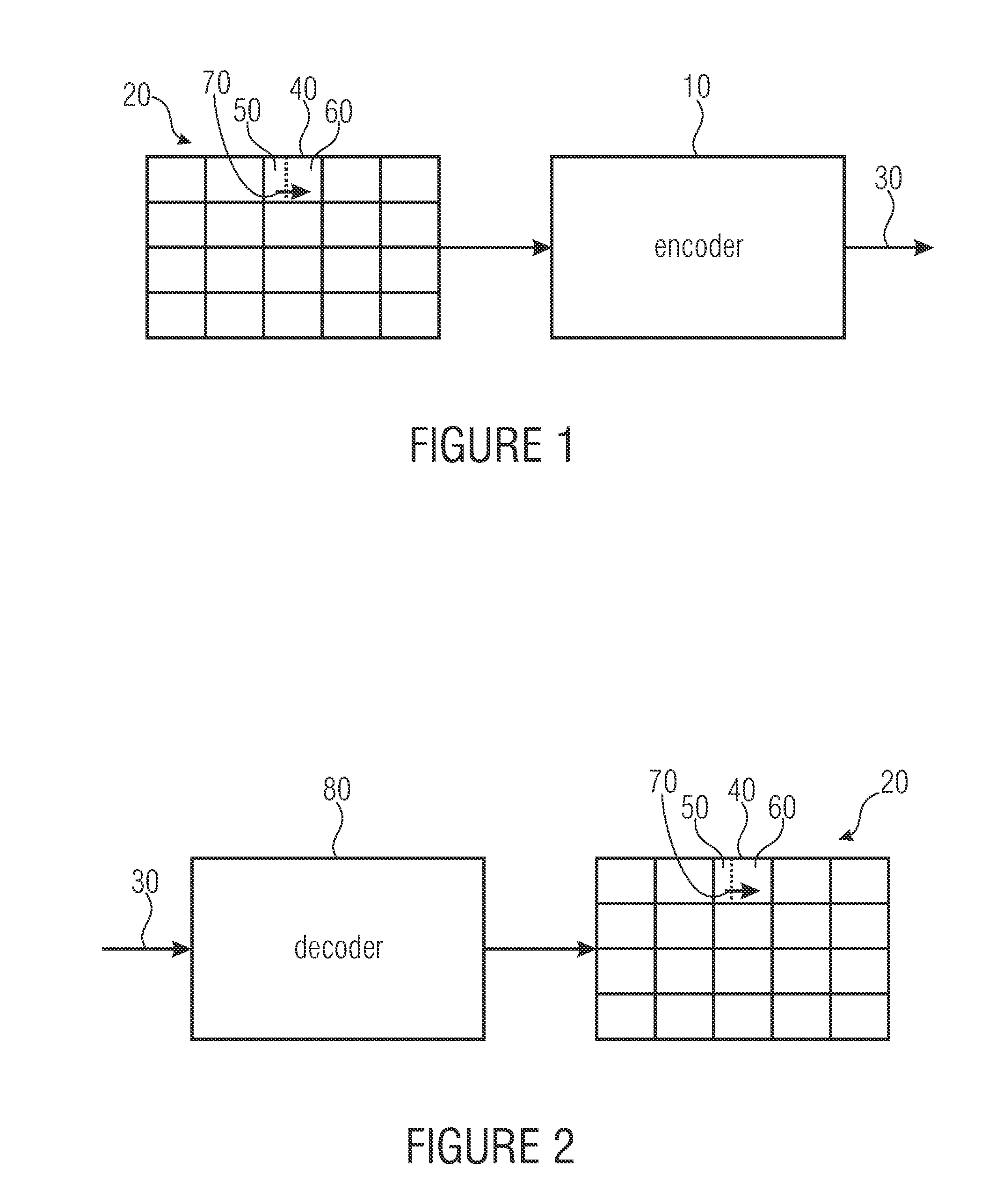
[0027]FIG. 1 shows an encoder 10 according to an embodiment of the present invention. The encoder 10 is configured to encode a picture 20 into a bit stream 30. Naturally, picture 20 could be part of a video in which case the encoder would be a video encoder.

[0028]The picture 20 comprises a block 40 which is currently to be encoded by encoder 10. As shown in FIG. 1, picture 20 may comprise more than one block 40. For example, the picture 20 may be sub-divided into a regular arrangement of blocks 40 so that the blocks 40 are arranged in rows and columns as ...


PUM


Abstract

A further coding efficiency increase may be achieved if for a current block of a picture, for which the bit stream signals one of supported partitioning patterns, a reversal of the partitioning by block merging is avoided. In particular, if the signaled one of the supported partitioning patterns specifies a subdivision of the block into two or more further blocks, a removal of certain coding parameter candidates for all further blocks, except a first further block of the further blocks in a coding order, is performed. Particularly, those coding parameter candidates are removed from the set of coding parameter candidates for the respective further block, the coding parameters of which are the same as coding parameters associated with any of the further blocks which, when being merged with the respective further block, would result in one of the supported partitioning pattern. This avoids redundancy between partitioning coding and merging coding.

Description

CROSS-REFERENCE TO RELATED APPLICATIONS[0001]This application is a continuation of copending International Application No. PCT / EP2011 / 067647, filed Oct. 10, 2011, which is incorporated herein by reference in its entirety, and additionally claims priority from U.S. Provisional Application No. 61 / 391,473, filed Oct. 8, 2010, which is also incorporated herein by reference in its entirety.BACKGROUND OF THE INVENTION[0002]The present application concerns picture and / or video coding and in particular codecs supporting block partitioning and block merging.[0003]Many picture and / or video codecs treat the pictures in units of blocks. For example, predictive codecs use a block granularity in order to achieve a good compromise between very precisely set prediction parameters set at a high spatial resolution with, however, spending too much side information for the prediction parameters on the one hand and too coarsely set prediction parameters, causing the amount of bits necessitated to encode...

Claims


Application Information

Patent Timeline
IPC IPC(8): H04N7/26
CPCH04N19/00072H04N19/119H04N19/147H04N19/176H04N19/196H04N19/46H04N19/61H04N19/70H04N19/93H04N19/463H04N19/52H04N19/44H04N19/157
Inventor HELLE, PHILIPPSCHWARZ, HEIKOMARPE, DETLEVWIEGAND, THOMASOUDIN, SIMONBROSS, BENJAMIN
Owner GE VIDEO COMPRESSION LLC
Why Eureka
Try Eureka