Apparatus for surgery

a technology for surgery and apparatus, applied in the field of surgical instruments and apparatuses, can solve the problems of long standing, surgeons' hands may not be used to directly hold and move, and surgeons get very tired during surgery, and achieve the effect of convenient use and affordableness

Inactive Publication Date: 2013-11-07
KIM YOUNG JAE
View PDF10 Cites 30 Cited by
  • Summary
  • Abstract
  • Description
  • Claims
  • Application Information

AI Technical Summary

Benefits of technology

[0013]The present disclosure provides a endoscopic / laparoscopic surgical system that is affordable and easy to use.

Problems solved by technology

Therefore, in a complicated surgery, the surgeon needs to perform the operation in a standing posture for several hours, and thus, the surgeon gets very tired during the surgery.
Therefore, during a laparoscopic surgical procedure, a surgeon's hands may not be used to directly hold and move the surgical instruments.
Similar to the conventional surgery, a surgery performed using this type of surgical instrument coupled to the controller may also require long standing by the surgeon, and the surgeon performing the surgery may also get tired after a few hours of surgery.
Further, when several instruments need to be inserted into the body together, more than one person may be required to perform the surgery such that each person holds or operate each instrument since one person cannot hold or handle all the instruments.
These robotic systems allow more complex movements of surgical instruments in a limited space due to additional degrees of freedom available to the surgeon.
However, such robotic systems are very costly (more than $ 1 million), and thus, not many hospitals or doctors can afford such expensive robotic systems.
Further, such robotic systems, which are motorized, electrically driven and often computer-assisted, are very complex and lack force feedback to the surgeon.
Further, one disadvantage of the portable mechanical surgical instruments is that it may be more tiring for a surgeon to perform surgery with the portable mechanical surgical instruments than to perform a surgery using the robotic systems because the surgeon performs the surgery in a standing position when using the portable mechanical surgical instruments while the surgeon may sit in a chair in front of a control station when using the robotic systems.
On the other hand, in general, the robotic systems require using only surgical instruments specifically manufactured to be used with the robotic system and such surgical instruments that are compatible with the robotic systems are very costly, and thus, the cost of maintenance is very high.

Method used


Image

  • Apparatus for surgery
  • Apparatus for surgery
  • Apparatus for surgery

Examples


Embodiment Construction

[0058]In the following detailed description, reference is made to the accompanying drawing figures which form a part hereof, and which show by way of illustration example embodiments of the invention. It is to be understood by those of ordinary skill in this technological field that other embodiments may be utilized, and structural, electrical, as well as procedural changes may be made without departing from the scope of the example embodiments of the invention described herein. Wherever possible, the same reference numbers will be used throughout the drawings to refer to the same or similar parts.

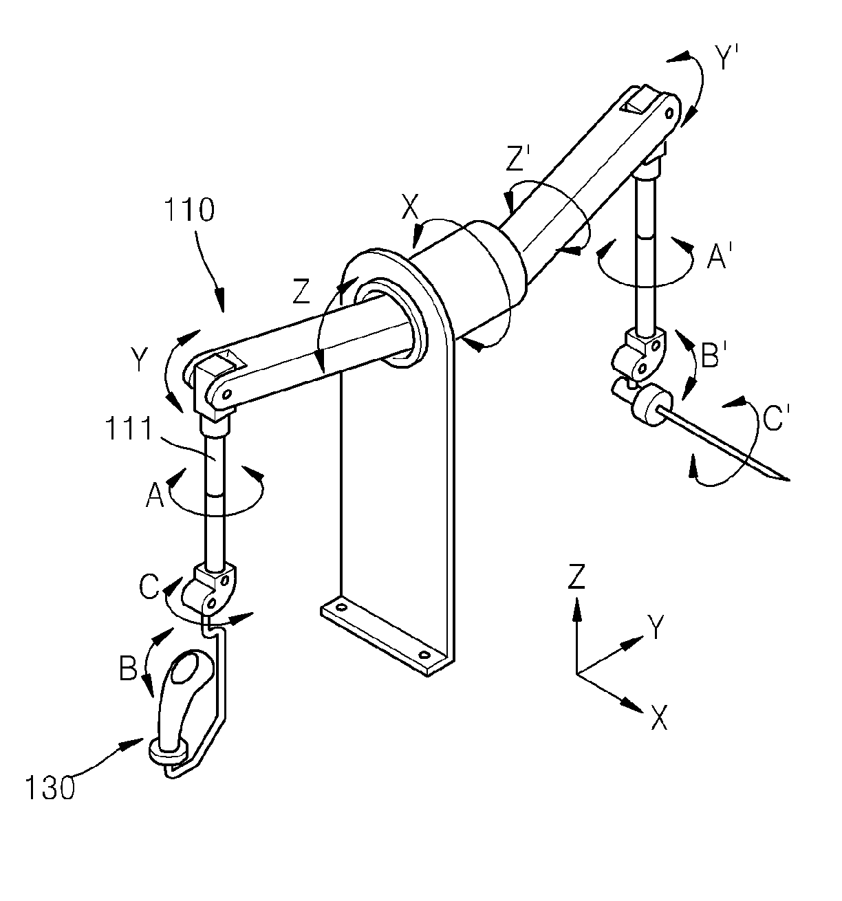
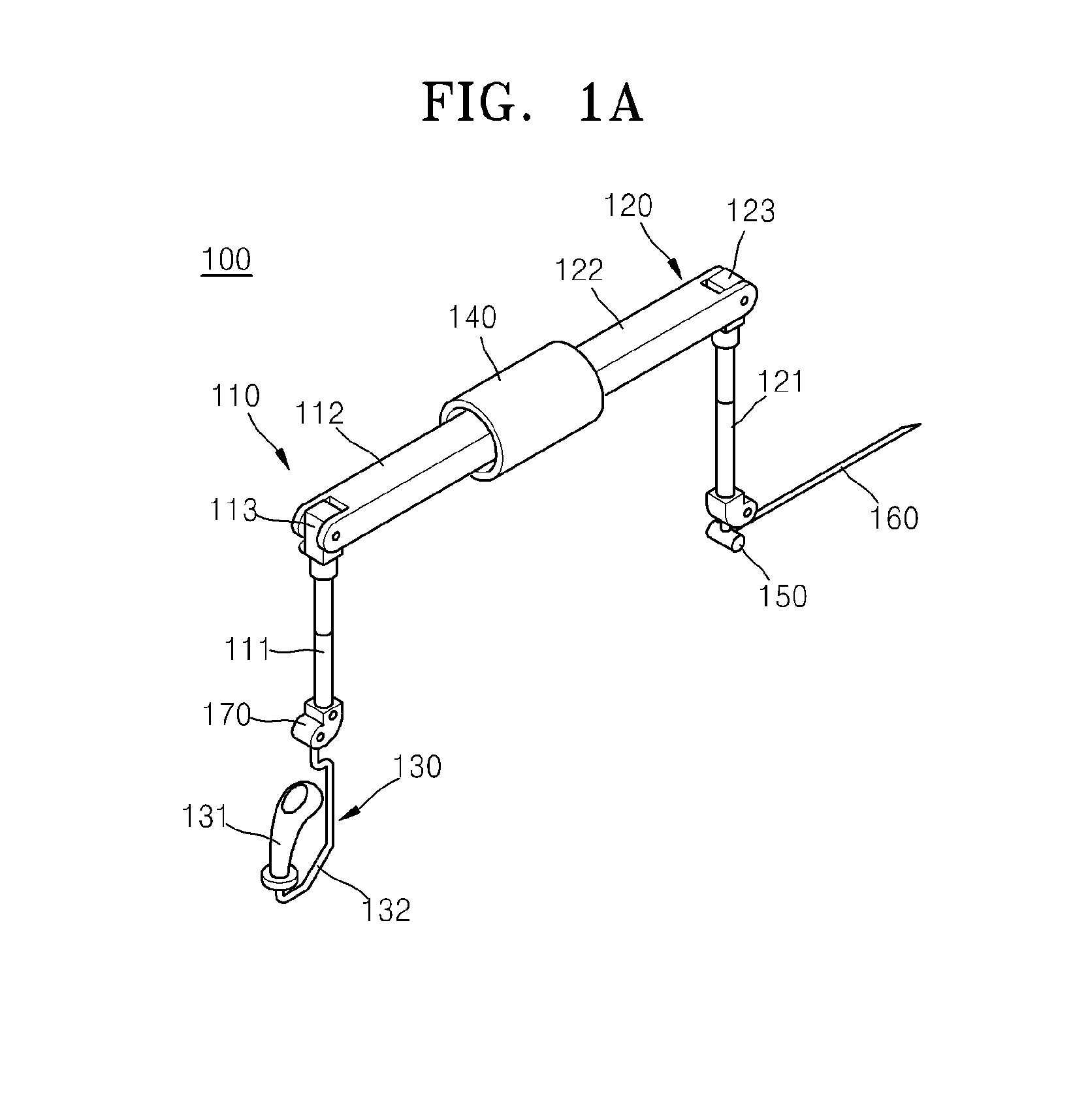
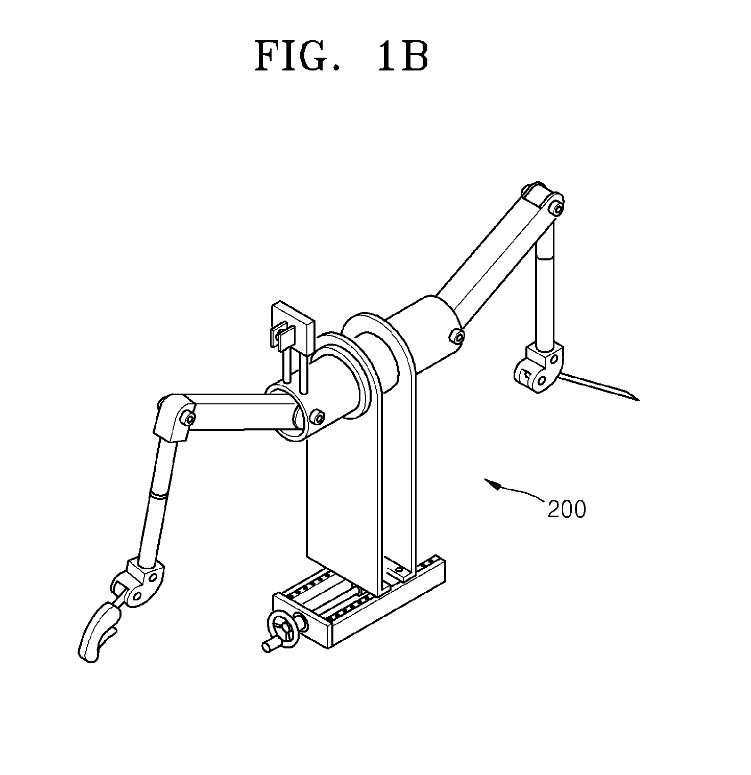
[0059]Referring to FIG. 1A, an apparatus 100 for manipulating an end-effector or surgical instrument 160 includes a master module 110 and a slave module 120. The master module 110 and the slave module 120 may be operatively connected by a transmission assembly 140 and the slave module 120 moves according to movement of the master module 110. In other words, the transmission assembly 140 tr...


PUM


Abstract

A surgical manipulator comprising: a master module configured to be controlled by a user; a slave module configured to move according to movement of the master module; and a transmission module comprising gears and configured to operably connect the master module and the slave module.

Description

CROSS REFERENCE TO RELATED APPLICATIONS[0001]Pursuant to 35 U.S.C. §119(e), this application claims the benefit of Provisional Application No. 61 / 618,528 filed on Mar. 30, 2012, the contents of which are hereby incorporated by reference herein in their entirety.FIELD[0002]The present disclosure generally relates to a method and an apparatus for enhancing performance of minimally invasive surgery. In particular, the present disclosure relates to a mechanical manipulator for manipulating surgical instruments used in the minimally invasive or endoscopic surgery. The present disclosure more particularly relates to a surgical instrument which provides a high degree of dexterity and precision, allowing easy control of surgical instruments and improving performance of minimally invasive surgical procedures.DESCRIPTION OF THE RELATED ART[0003]In a conventional operation, an incision is made on a body of a patient such that a surgical instrument and sometimes a hand of a surgeon can be place...

Claims


Application Information

Patent Timeline
Patent Type & Authority Applications(United States)
IPC IPC(8): A61B19/00
CPCA61B19/2203A61B2017/00973A61B34/70
Inventor KIM, YOUNG JAEKIM, NATHANAEL
Owner KIM YOUNG JAE
Why Eureka
Try Eureka