Apparatus and method for displaying a blind spot

a technology of blind spots and apparatus, applied in the field of apparatus and methods for displaying blind spots, can solve the problems of difficult parking, and driver who is not accustomed to parking can hit an obstacle hidden in the front or rear, so as to achieve safe parking environment and safe driving environmen

Active Publication Date: 2013-11-14
WISE AUTOMOTIVE CORP
View PDF7 Cites 32 Cited by
  • Summary
  • Abstract
  • Description
  • Claims
  • Application Information

AI Technical Summary

Benefits of technology

[0025]The present invention is advantageous in that information on blind spots in the front, rear, and sides of a vehicle that are hidden by a vehicle body and thus rarely seen within a field of view of a driver when the driver drives the vehicle can be provided to the driver by displaying one or more i

Problems solved by technology

However, the driver feels difficult to secure a field of view and to park the vehicle if obstacles are located in the blind spots because several obstacles are present in the surroundings of the vehicle 10.
Furthermore, a driver who is not accustomed to parking can hit an obstacle hidden in the front or rear of a vehicle when parking the vehicle.
Even a driver who is accustomed to parking can park his vehicle while raising his head and watching the

Method used


Image

  • Apparatus and method for displaying a blind spot
  • Apparatus and method for displaying a blind spot
  • Apparatus and method for displaying a blind spot

Examples


first embodiment

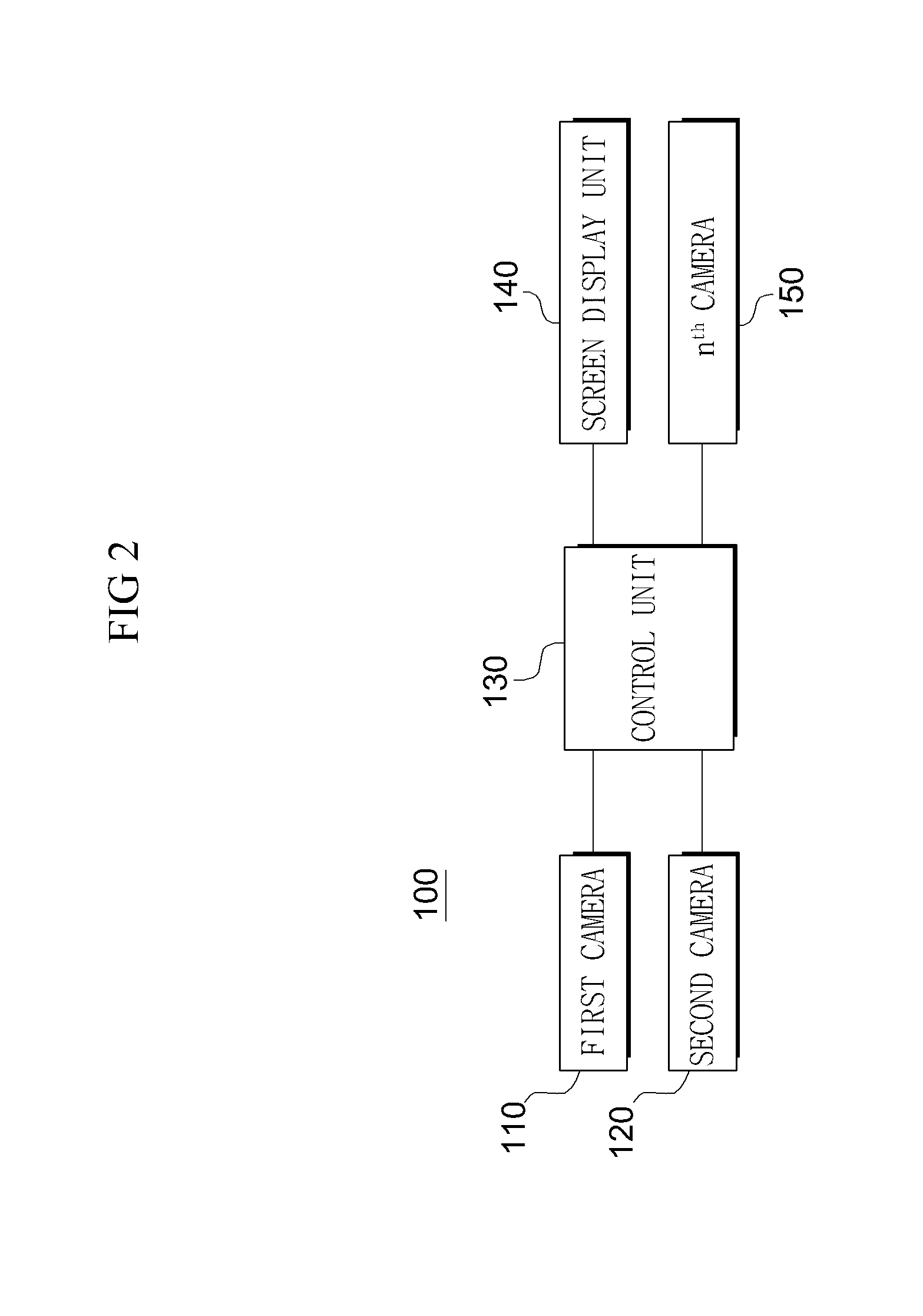
[0039]FIG. 2 is a block diagram showing an embodiment of an apparatus for displaying a blind spot in accordance with the present invention, FIG. 3 is an exemplary diagram showing an operating process of the apparatus for displaying a blind spot in accordance with the present invention, FIG. 4 is an exemplary diagram showing another operating process of the apparatus for displaying a blind spot in accordance with the present invention, and FIG. 5 is an exemplary diagram in which a rear past image and a current image captured by the apparatus for displaying a blind spot in accordance with the present invention are merged.

[0040]As shown in FIG. 2 to FIG. 5, the apparatus for displaying a blind spot 100 in accordance with the present invention includes a first camera 110, a second camera 120, and an nth camera 150 as imaging means for providing images of the surroundings of a vehicle, a control unit 130, and a screen display unit 140.

[0041]The first camera 110 is an element installed in...

second embodiment

[0102]FIG. 10 is a block diagram showing another embodiment of an apparatus for displaying a blind spot in accordance with the present invention. The second embodiment relates to a construction for detecting images of the surroundings of a vehicle from devices other than cameras installed in the vehicle and displaying a blind spot based on the detected images.

[0103]As shown in FIG. 10, an apparatus for displaying a blind spot 600 in accordance with the second embodiment includes a GPS navigation system 610 and an external information reception unit 620 as imaging means for providing images of the surroundings of a vehicle, a control unit 630, and a screen display unit 640.

[0104]The GPS navigation system 610 is installed in the vehicle. The GPS navigation system 610 receives information on the position of the vehicle from a GPS receiver, detects information on a current position of the vehicle based on the received information, reads a map image or real image of a corresponding posit...


PUM


Abstract

The aim of the present invention is to provide an apparatus and method for displaying a blind spot, which involve displaying at least one image of the surroundings of a vehicle, said image being provided by an imaging unit including a camera, a GPS navigation system, and/or a street-view receiver, so as to provide a driver with information on the blind spots of a front portion, a rear portion, and a side portion of a vehicle that are hidden by said vehicle and thus not easily seen within the field of view of the drive during the travel of the vehicle.

Description

TECHNICAL FIELD[0001]The present invention relates to an apparatus and method for displaying a blind spot in the surroundings of a vehicle and, more particularly, to an apparatus and method for providing a driver with information on blind spots in the front, rear, and sides of a vehicle that are hidden by a vehicle body and thus rarely seen within a field of view of the driver when the driver drives the vehicle by displaying one or more images of the surroundings of the vehicle provided by a camera, a GPS navigation system, and / or a street-view receiver.BACKGROUND ART[0002]In general, a vehicle runs on a road by using a motor, such as an engine installed in a vehicle body, as a power source. A vehicle is an apparatus for carrying persons or goods or performing various tasks. The driver of a vehicle safely drives the vehicle while watching a driving direction.[0003]In a common vehicle 10, however, as shown in FIG. 1, a blind spot 20 is formed because a front portion near the vehicle ...

Claims


Application Information

Patent Timeline
IPC IPC(8): G08G1/16
CPCG08G1/167B60R1/00B60R2300/70B60R2300/802
Inventor PARK, JAE-HONG
Owner WISE AUTOMOTIVE CORP
Why Eureka
Try Eureka