Use of survival modeling methods with pipeline inspection data for determining causal factors for corrosion under insulation

a survival modeling and pipeline inspection technology, applied in the field of pipeline inspection, can solve the problems of slow contribution of pipeline joints to corrosion of the outer surfaces of pipeline joints, pipeline joints b, b> may be exposed to environmental moisture,

Inactive Publication Date: 2013-11-14
BP CORP NORTH AMERICA INC +1
View PDF4 Cites 10 Cited by
  • Summary
  • Abstract
  • Description
  • Claims
  • Application Information

AI Technical Summary

Problems solved by technology

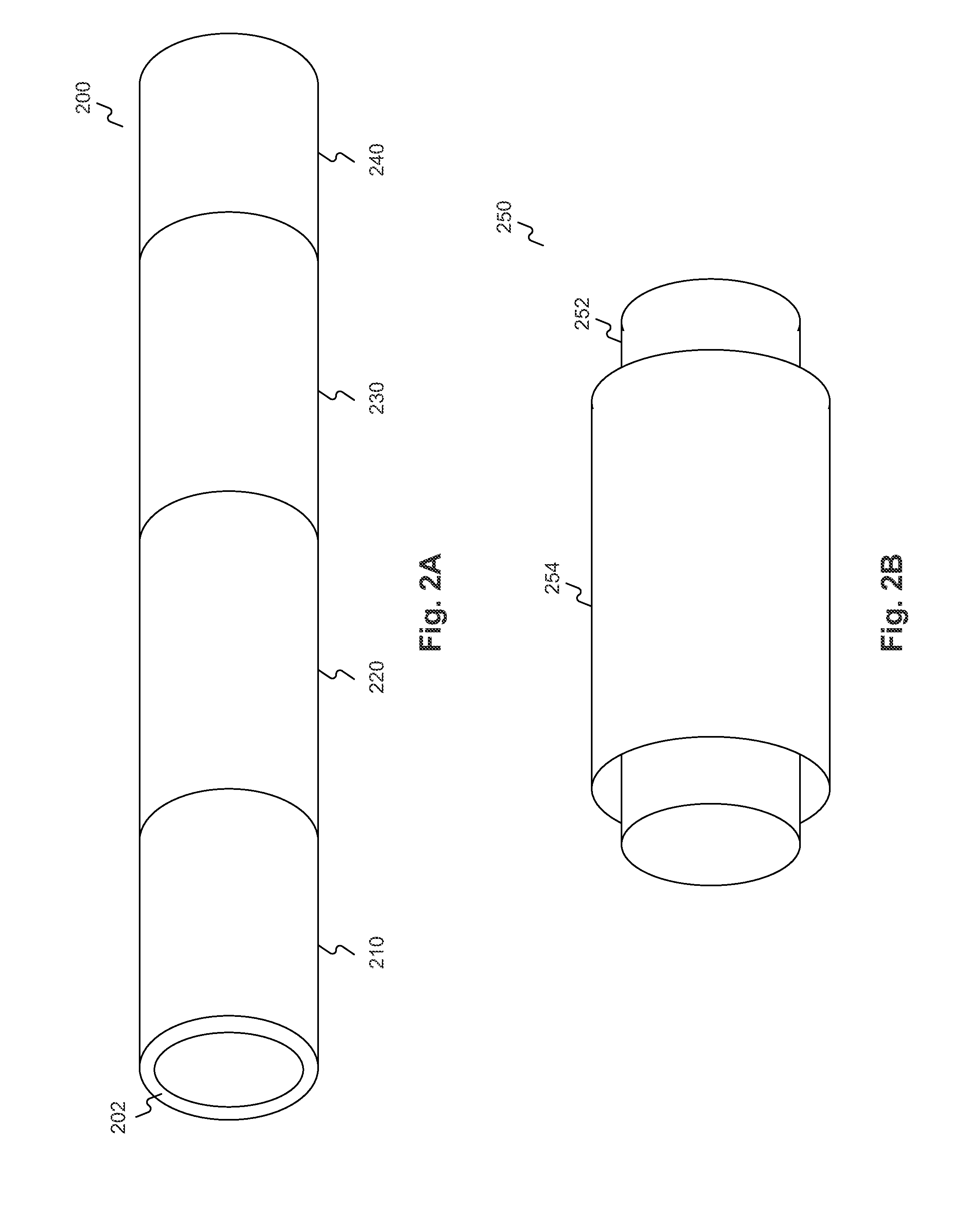
However, because the process of applying insulation to pipeline joint 340 typically must take place outdoors, in the field where the larger pipeline structure is being assembled, pipeline joint 340 may be exposed to environmental moisture, which may remain on the outer surfaces of the pipeline segments, even after insulation is applied.
Even if such moisture is minor or initially undetectable, over a long period of time, it can slowly contribute to corrosion of the outer surfaces of pipeline joints, a process known as corrosion under insulation (CUI).
Although any area of a pipeline segment can suffer from CUI, the environmental exposure of pipeline joints prior to insulation may render them generally more susceptible to CUI.
In addition, other events or conditions may introduce moisture to the outer surfaces of pipeline segments or joints, such as routine maintenance or deterioration of an insulation layer due to environmental conditions.
If CUI is permitted to run its course, it can eventually corrode a pipeline wall to the point of losing containment capacity, thus allowing materials transported through a pipeline to leak or escape.
In addition to the economic implications of losing valuable commodities, leaking materials may remain trapped under the lagging of corroded pipelines, which may force the leaking materials to the external surfaces of adjacent containment surfaces and, thus accelerate CUI for other pipeline segments or joints.
However, several barriers to efficiently detecting CUI in pipeline joints exist.
As a result, it may not be feasible to inspect each of the tens of thousands of constituent pipeline joints in the pipelines themselves, or to inspect them with sufficient frequency that would allow an inspection team to detect CUI inception before it progresses to the point of rendering a pipeline joint inoperable.
In this example, even an otherwise statistically reliable sampling of pipelines and pipeline locations may not be effective at detecting CUI in the pipeline joint, since an inspection at year six may not detect any corrosion and a subsequent inspection at year ten may be too late.
Moreover, in some production fields, the sheer number of individual pipeline joints can make it impossible to inspect each and every pipeline joint once, let alone on multiple occasions as part of any kind of periodic inspection campaign.
Finally, even when a pipeline joint is found to be undergoing CUI, known techniques have not identified any reliable way of extrapolating from the conditions of the affected pipeline joint which other pipeline joints may similarly be affected by or even vulnerable to CUI in the near future.
This failure is typically due to the large number of differing attributes between distinct pipeline joints, pipelines, and locations, all of which can factor into an overall corrosion rate for a given pipeline joint.
Given the myriad number of variables, known techniques have not identified any meaningful way to correlate particular pipeline conditions with the effects of particular attributes, such that conclusions can be drawn concerning what attributes caused the condition or the likely condition of other pipeline joints having overlapping, but different, sets of attribute values.

Method used


Image

  • Use of survival modeling methods with pipeline inspection data for determining causal factors for corrosion under insulation
  • Use of survival modeling methods with pipeline inspection data for determining causal factors for corrosion under insulation
  • Use of survival modeling methods with pipeline inspection data for determining causal factors for corrosion under insulation

Examples


Embodiment Construction

[0033]The following detailed description refers to the accompanying drawings. Wherever possible, the same reference numbers are used in the drawings and the following description to refer to the same or similar parts. While several exemplary embodiments and features of the present disclosure are described herein, modifications, adaptations, and other implementations are possible, without departing from the spirit and scope of the present disclosure. Accordingly, the following detailed description does not limit the present disclosure. Instead, the proper scope of the present disclosure is defined by the appended claims.

[0034]FIG. 4 is a diagram depicting exemplary hardware componentry of a computing system configured to perform the described embodiments, consistent with certain disclosed embodiments. System 400 can include one or more microprocessors 410 of varying core configurations and clock frequencies; one or more memory devices or computer-readable media 420 of varying physica...


PUM


Abstract

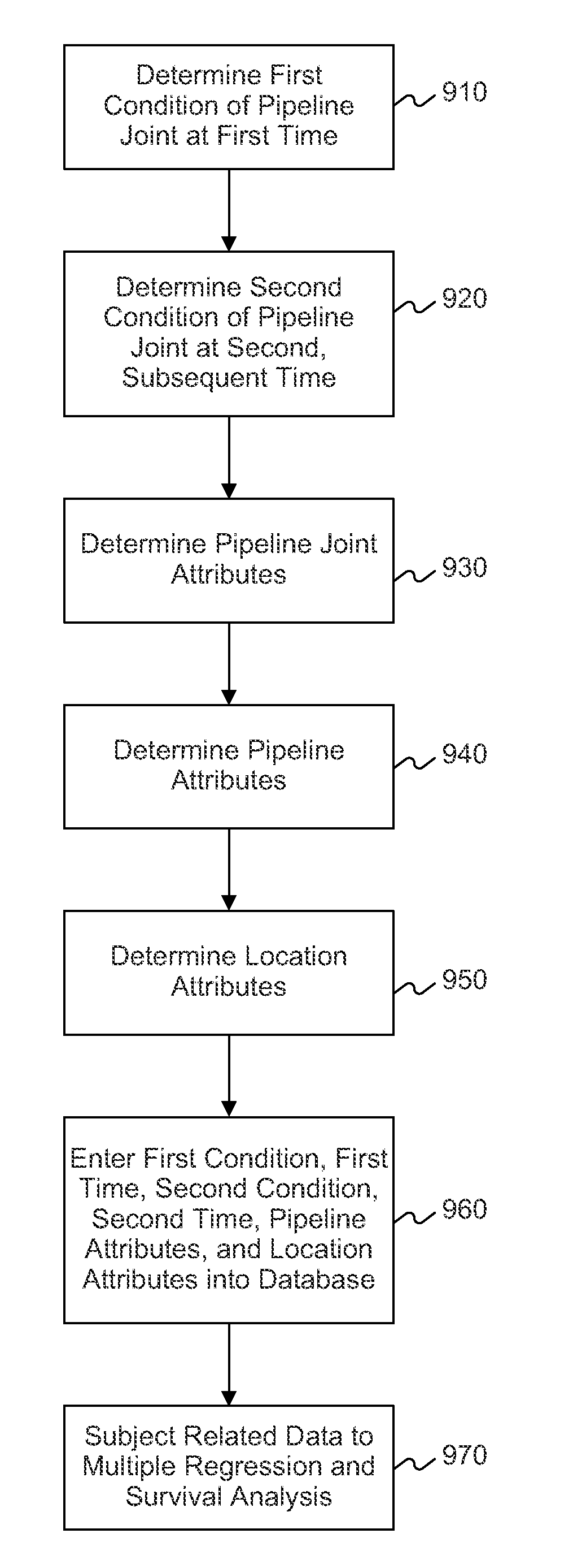
Methods and systems for using survival modeling methods with pipeline inspection data to determine causal factors for corrosion under insulation comprise determining a first corrosion condition of a pipeline joint at a first time; determining a second corrosion condition of the pipeline joint at a second, subsequent time; determining joint attributes, pipeline attributes, and location attributes associated with the pipeline joint; and repeating the process for a plurality of pipeline joints in one or more pipelines. This information is fed into a multiple regression and survival analysis process that determines regression coefficients reflecting the estimated degrees to which various factors contribute to corrosion under insulation. The survival analysis also determines one or more survival models capable of predicting when a given pipeline joint is likely to transition from a first corrosion state to a different second corrosion state, given values for its various attributes.

Description

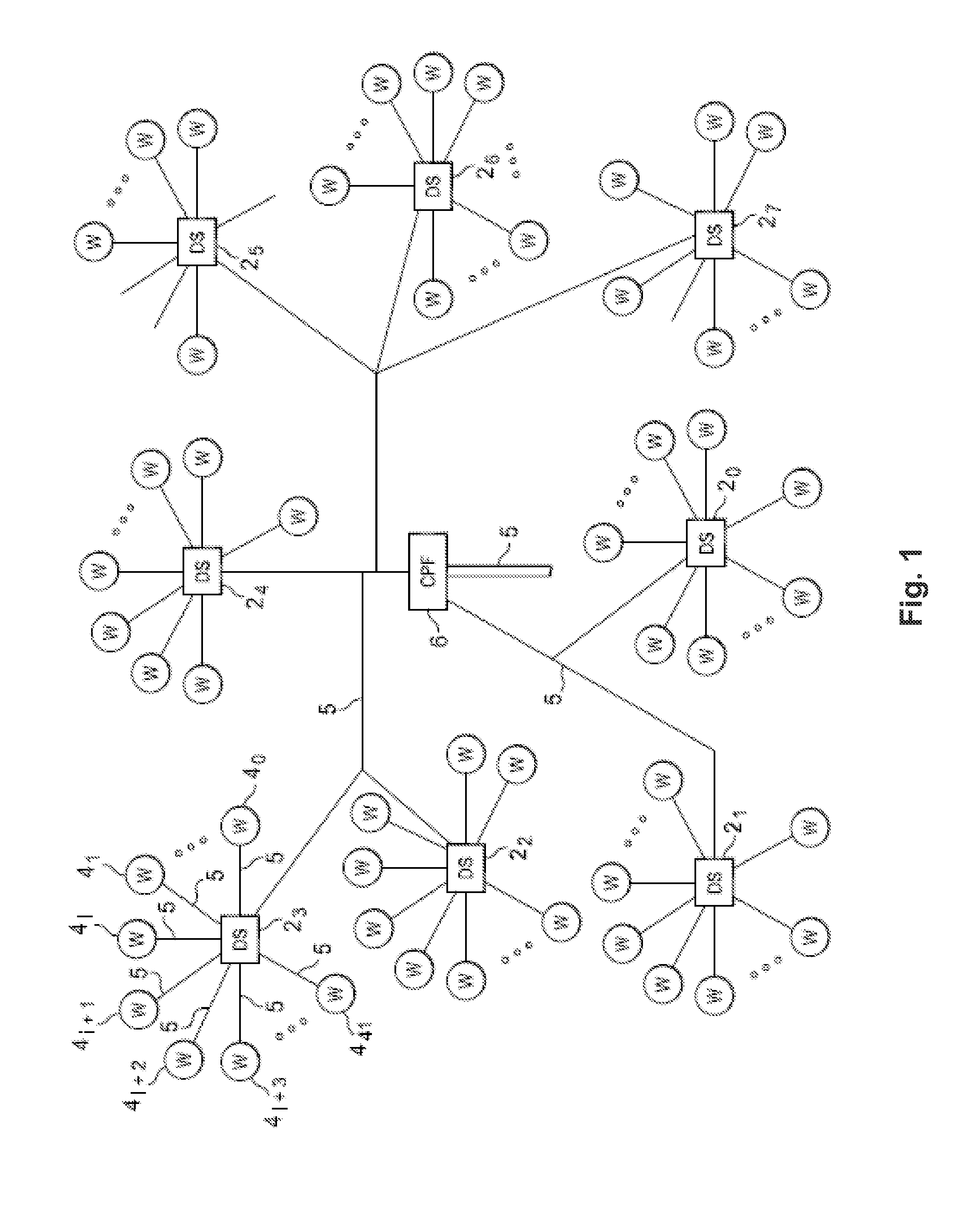
TECHNICAL FIELD[0001]The present disclosure relates generally to the field of pipeline inspection, and is more specifically directed to using survival modeling analysis to predict corrosion under insulation for a plurality of pipeline joints.BACKGROUND[0002]In the energy industry, it is frequently necessary to transport large amounts of oil and natural gas over long distances—for example, from one or more drilling and extraction sites to one or more refineries. Typically, such transport is accomplished using large networks of oil or natural gas pipelines that, together, constitute an oil and gas production field. FIG. 1 depicts an exemplary oil and gas production field, for purposes of illustration.[0003]As depicted in FIG. 1, a production field can include multiple wells 4, deployed at various locations within the field, from which oil and gas products are extracted. Each well 4 can be connected to a drill site 2 in its locale by way of a pipeline 5. By way of example, eight drill ...

Claims


Application Information

Patent Timeline
Patent Type & Authority Applications(United States)
IPC IPC(8): G06G7/48
CPCG06F30/00G06F2113/14G06F2119/04
Inventor BAILEY, RICHARD S.SPRAGUE, KIP P.ZIEGEL, ERIC
Owner BP CORP NORTH AMERICA INC
Why Eureka
Try Eureka