Device for the contactless flow measurement of fluids in flexible tubes

a flexible tube and fluid flow technology, applied in the direction of measuring devices, volume/mass flow by dynamic fluid flow effect, instruments, etc., can solve the problem of crosstalk between signals on the connection line, and achieve the effect of avoiding negative influences on the sending, improving the measuring quality, and enlarged in the cross-section

Active Publication Date: 2013-11-21
SONOTEC ULTRASCHALLSENOSORIK HALLE
View PDF16 Cites 34 Cited by
  • Summary
  • Abstract
  • Description
  • Claims
  • Application Information

AI Technical Summary

Benefits of technology

[0015]An outstanding feature of the invention is that the measuring channel may be enlarged in its cross-section—without changing its width—, starting from a square up to a standing rectangle, by the modular exchange of the base plate, which limits the measuring channel and the measuring cell on the bottom side, which allows to detect flexible tubes with a low outside diameter, from at least 3.5 mm and beyond, within defined limits.
[0016]Therein, the dimensions of the measuring cell, consisting in particular of the ceramics integrated into the lateral parts at a defined distance, remain unchanged to the extent technically reasonable. The ceramics are in particular designed as composite ceramics, and the individual elements of the measuring cell are not connected to each other in a compact casting. A joint casting with the electronic evaluation system, which is located below the measuring cell in the installation space for electronic modules, is not present either. Such decoupled design of the device, which may also be regarded as a miniaturisation in this order, avoids negative influences on the sending and receiving of measuring signals by cross-talk of the ceramics.
[0017]In addition, for improving the measuring quality, it is provided that the compact housing of the device together with the hinged cover is made of a material which provides shielding against electromagnetic waves from the environment. An appropriate plastic material is suitable for this.

Problems solved by technology

The previously known solutions of the prior art, as exemplified above, make use of an arrangement of clamp-on sensors in which transmitter / receiver transducer and the electronic evaluation system are physically separated, which may cause crosstalk of the signals on the connection line between them.

Method used


Image

  • Device for the contactless flow measurement of fluids in flexible tubes
  • Device for the contactless flow measurement of fluids in flexible tubes
  • Device for the contactless flow measurement of fluids in flexible tubes

Examples


Embodiment Construction

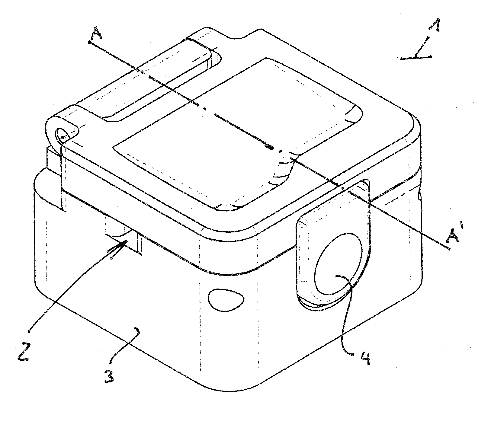
[0036]According to FIG. 1, the device is illustrated as a sensor 1 with a compact housing 3 with a closed hinged cover 17, wherein a tube inlet and a tube outlet 5, 6, leading into the inside of the housing 3 in a defined position, form a measuring channel 2 on the left and on the right under the hinged cover 17 in the upper area of the lateral walls of the housing 3. In this embodiment, the measuring channel 2 has a square cross-section, to which fits a flexible tube 18 by means of slight mechanical pressure when the hinged cover 17 is closed. This generates a largest possible surface for coupling the sound signals into a fluid flowing through the flexible tube 18. The deformation of the flexible tube 18 is illustrated by FIG. 5.

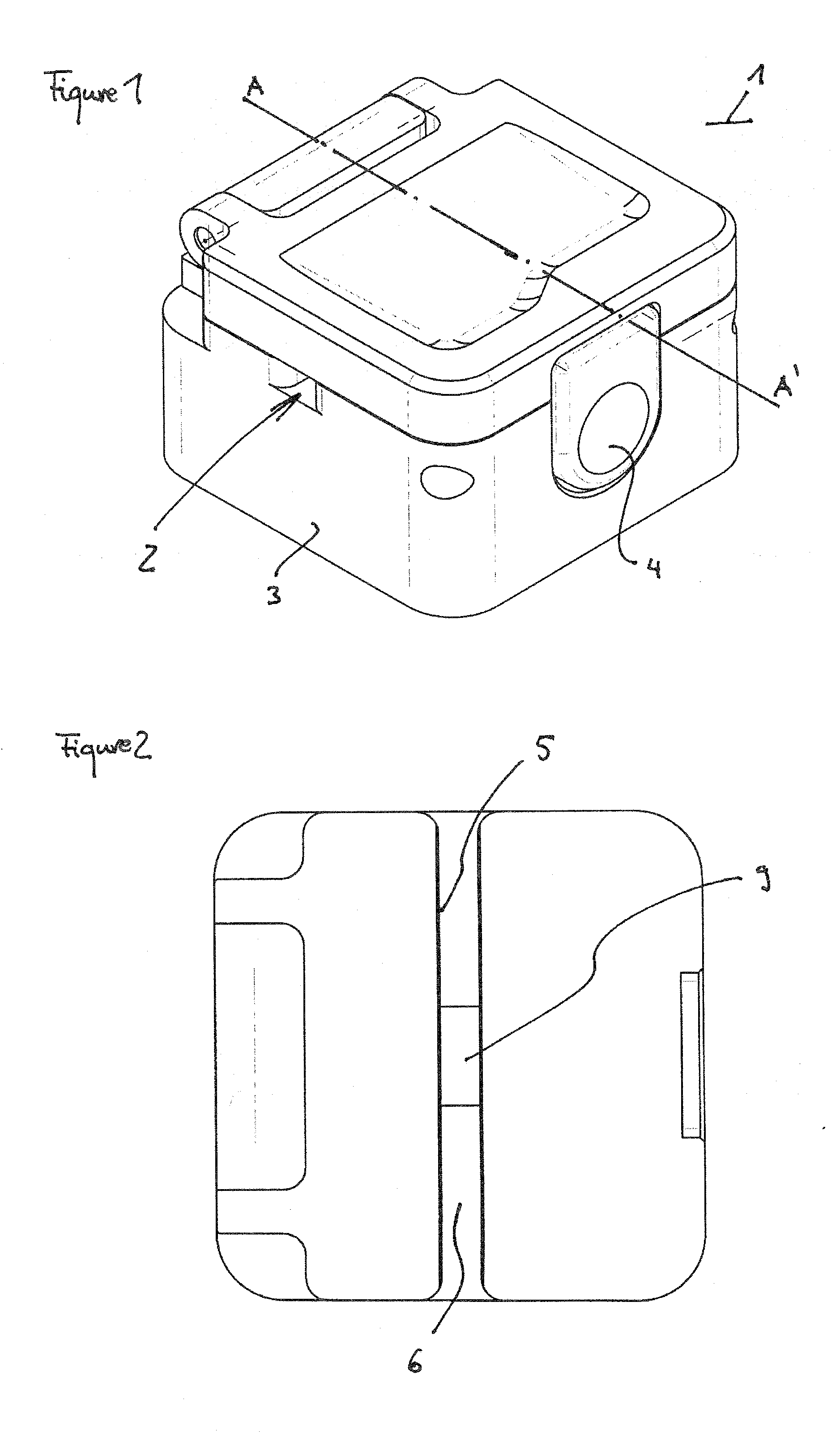
[0037]FIG. 2 shows a top view of the length of the measuring channel 2 with tube inlet and tube outlet 5, 6, wherein the measuring cell 9 is arranged centrally in the middle of the measuring channel 2. The measuring cell 9 consists of ceramics, that is piez...


PUM


Abstract

The invention relates to a device for the contactless flow measurement of fluids in flexible tubes.

Description

FIELD OF THE INVENTION[0001]The invention relates to a device for the contactless flow measurement of fluids in flexible tubes, the diameter of which is clearly below 12 mm. The measurement of the flow of sound-transparent liquids by non-invasive means on flexible tubes is known from prior art, and it is performed up to the diameter ranges as stated above, with the transit time difference method also representing a known method for working with such a device.BACKGROUND OF THE INVENTION[0002]Prior art may be exemplified by products of the companies em-tec GmbH, D-86923 Finning or Transonic Systems Inc., New York 14850, USA.[0003]Thus, the company em-tec GmbH offers a clamp-on transducer for measuring a flow in extracorporeal tubing systems, as available for checking on the website http: / / www.em-tec.de of said company. The sensor placed in a housing is clamped on a tube by a click closure, and the measurement is thus taken non-invasively. Applications can be found in medicine, e. g. i...

Claims


Application Information

Patent Timeline
Patent Type & Authority Applications(United States)
IPC IPC(8): G01F1/05
CPCG01F1/667
Inventor MUENCH, HANS-JOACHIMHORST-MEYER, SANTER ZURFRITSCHE, TOBIASKAHLE, JURGENKRAUSE, WERNERBADER, NICKI
Owner SONOTEC ULTRASCHALLSENOSORIK HALLE
Why Eureka
Try Eureka