Bicycle pedal assembly

Active Publication Date: 2013-11-28
HSIEH CHIN LONG +1
View PDF2 Cites 9 Cited by
  • Summary
  • Abstract
  • Description
  • Claims
  • Application Information

AI Technical Summary

Benefits of technology

[0008]An object of the invention is to provide a pedal assembly, which increase engagemen

Problems solved by technology

Although the engagement of the pedal and cleat appears secure, in fact it is not secure enough because there are only two engagement points at the front end and rear end and the cleat still can horizontally rotate

Method used


Image

  • Bicycle pedal assembly
  • Bicycle pedal assembly
  • Bicycle pedal assembly

Examples


Example

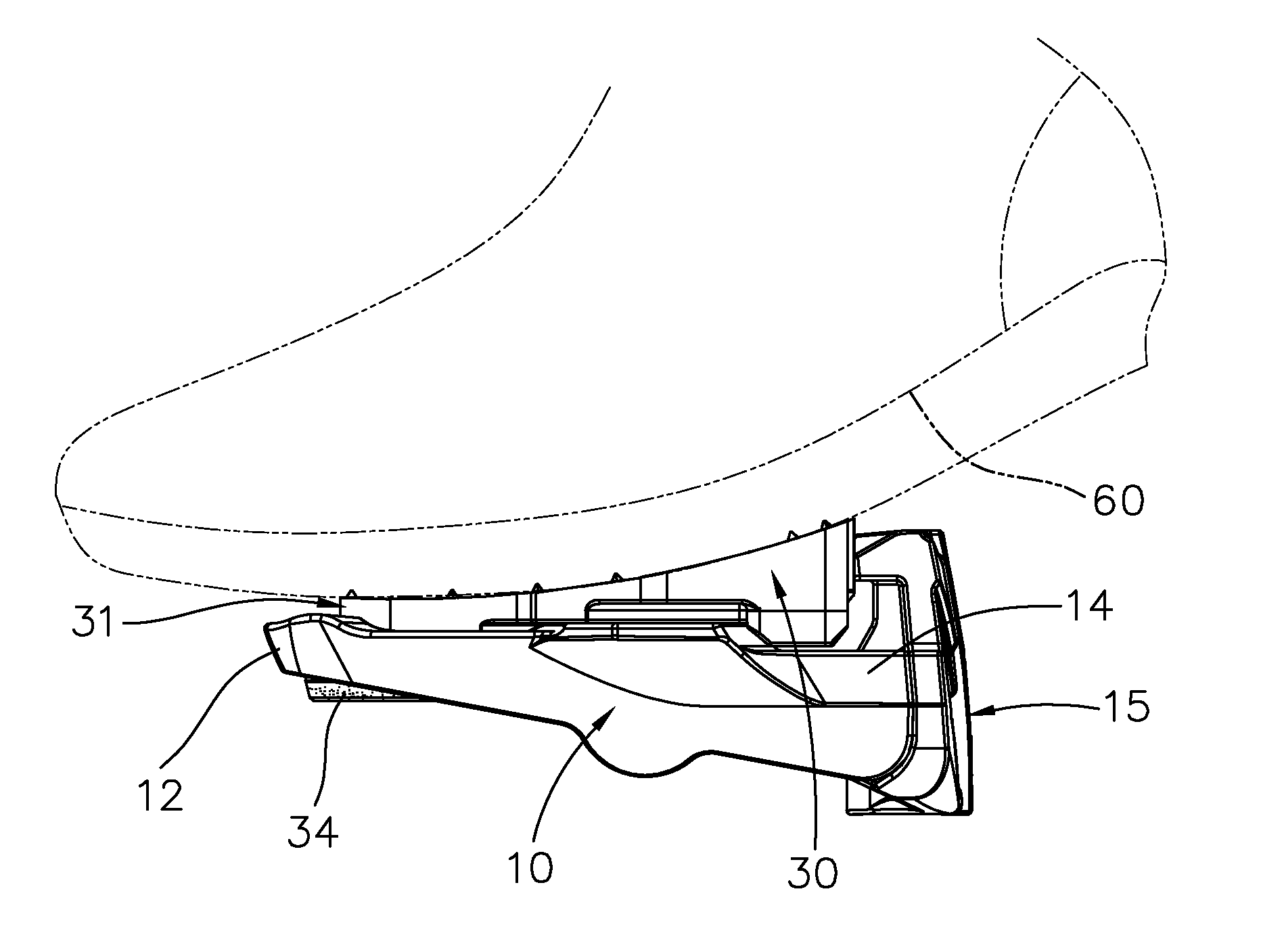
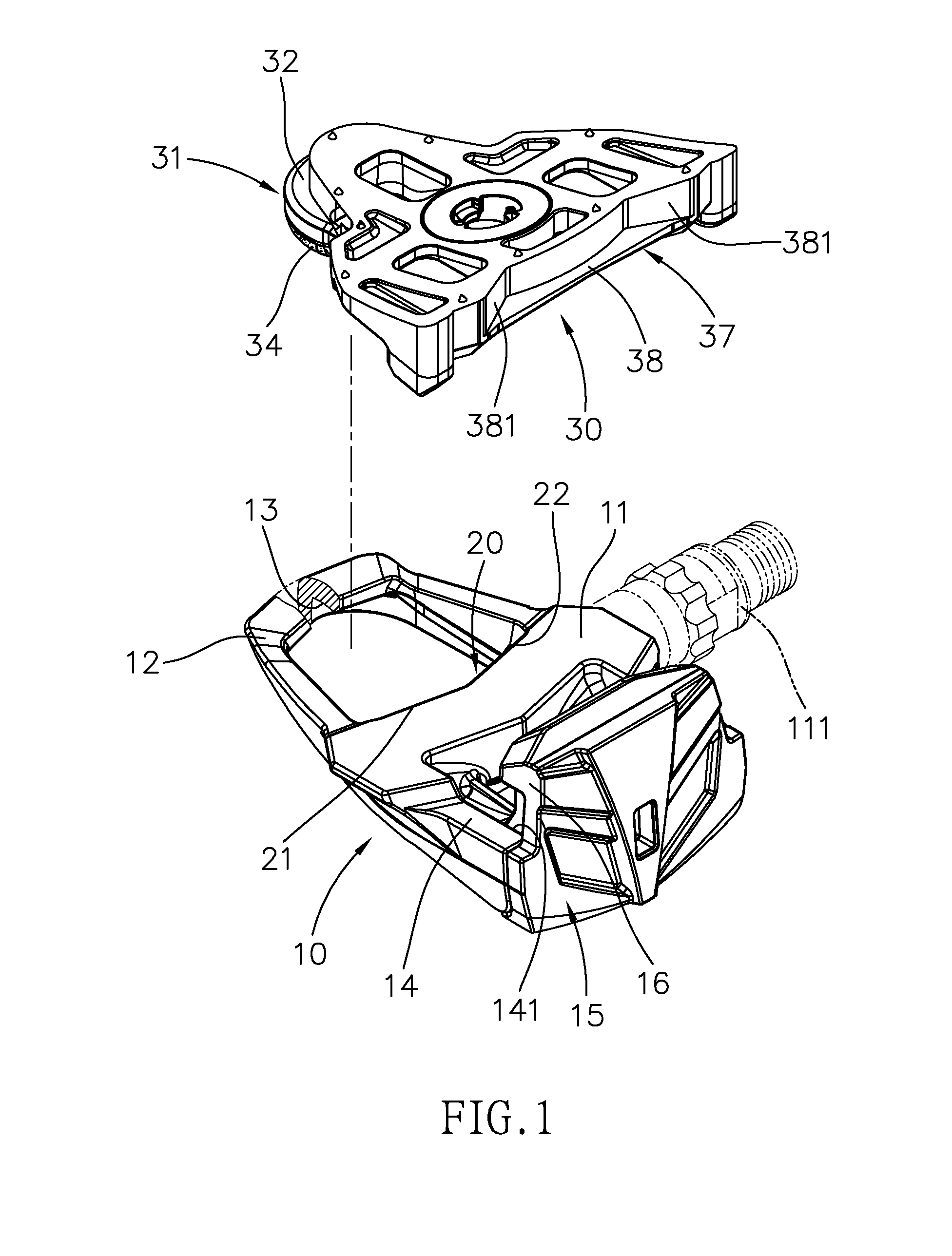
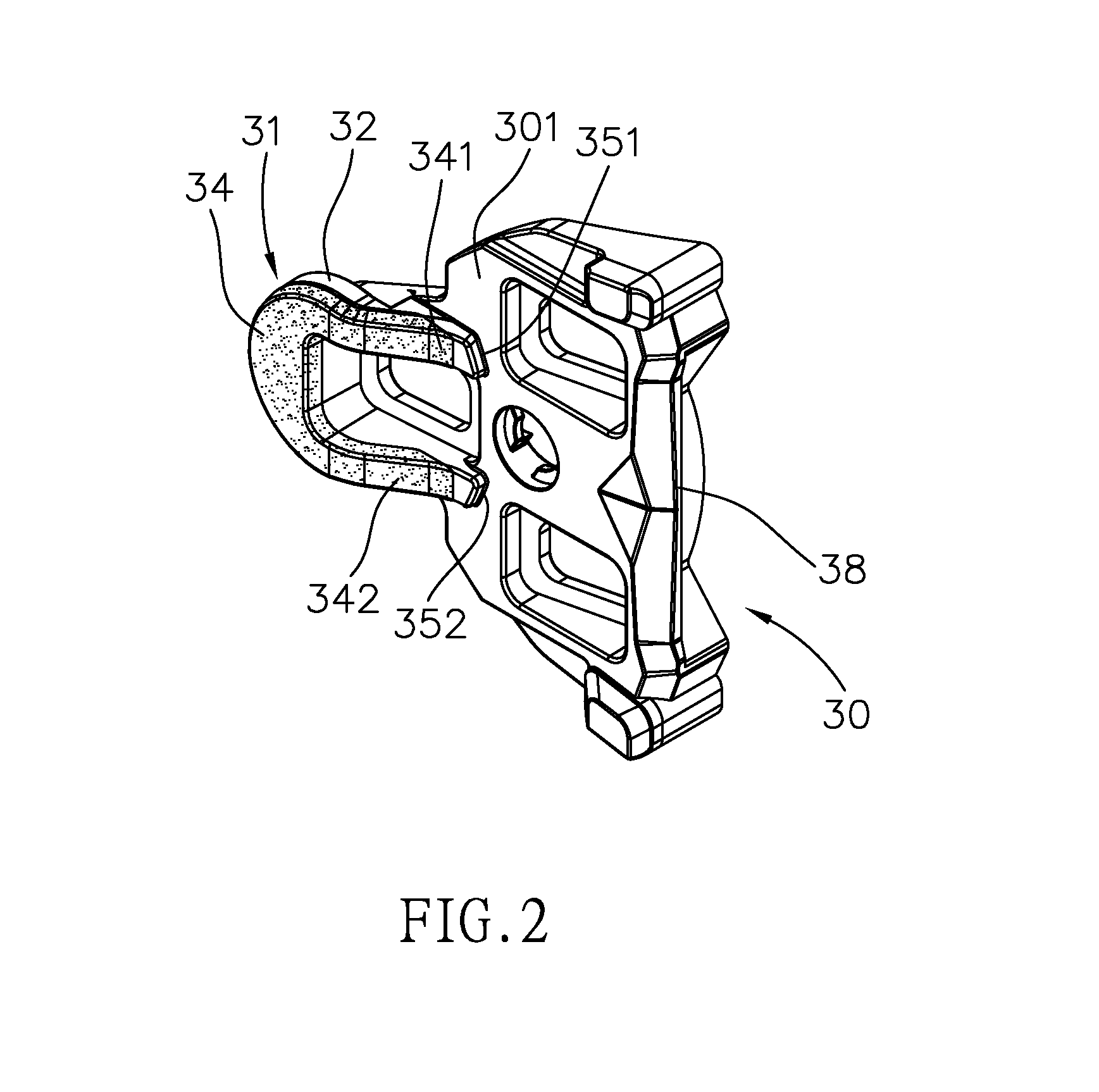
[0021]Please refer to FIG. 1. The pedal assembly of the invention includes a pedal 10 and a cleat 30. The pedal 10 has a spindle portion 11, a front portion 12 with a front engagement member 13, a rear portion 14 and a rear engagement member 15 movably coupled to the rear portion 14. The cleat 30 can be engaged between the front engagement member 13 and the rear engagement member 15.

[0022]Please refer to FIGS. 1 and 3. A spindle 111 is rotatably received in the spindle portion 11. The front and rear portions 12, 14 separately oppositely extend from the spindle portion 11. The rear portion 14 is formed with a connecting portion 141 for connecting the rear engagement member 15. The rear engagement member 15 has a hook 16. As shown in FIG. 4, a spring 151 is disposed between the rear engagement member 15 and the rear portion 14. The front engagement member 13 is also like a hook in shape.

[0023]A front edge of the spindle portion 11 is formed with a concave V-shaped positioning side 20....


PUM


Abstract

The pedal assembly includes a pedal and a cleat. The pedal has a spindle portion, a front portion with a front engagement member, a rear portion and a rear engagement member movably coupled to the rear portion. The cleat has a front engagement end and a rear engagement end. A front edge of the spindle portion is formed with a V-shaped positioning side. A U-shaped pad is attached under the front engagement end. Two legs of the pad are protrudent from the bottom of the cleat, and ends of the legs are separately formed with two abutment surfaces. The abutment surfaces abut against the positioning side.

Description

BACKGROUND OF THE INVENTION[0001]1. Technical Field[0002]The invention relates to a pedal of bicycle, particularly to a step-in or clipless pedal.[0003]2. Related Art[0004]In recently years, bicycling becomes a worldwide popular form of recreation, sport and transportation. Depending upon different purposes of bicycling, there are many kinds of bicycles, such as road bikes, mountain bikes, folding bikes, etc. Whether bicycles are used for recreation, transportation or competition, the bicycle industry always keeps improving all components bicycle. An important component of a bicycle, especially for road bikes, is the step-in pedal, as known as clipless pedal.[0005]The step-in or clipless pedal releasably engages with a cleat fastened under a sole of a cyclist's shoe. The clipless pedal has a spindle that can be screwed on a crank arm, a pedal body which is rotatably mounted on this spindle, and a cleat engagement mechanism on the pedal body. In a road bike, a racing clipless pedal t...

Claims


Application Information

Patent Timeline
IPC IPC(8): B62M3/00A43B5/14
CPCB62M3/086
Inventor HSIEH, CHIN-LONGHUANG, TSUNG-TSE
Owner HSIEH CHIN LONG
Why Eureka
Try Eureka