Eureka AIR delivers breakthrough ideas for toughest innovation challenges, trusted by R&D personnel around the world.

Piezoelectric energy harvesting array and method of manufacturing the same

Inactive Publication Date: 2013-11-28
ELECTRONICS & TELECOMM RES INST
View PDF5 Cites 18 Cited by
  • Summary
  • Abstract
  • Description
  • Claims
  • Application Information

AI Technical Summary

Benefits of technology

The patent describes a way to make a piezoelectric energy harvesting array by connecting multiple devices to a base and tuning their resonant frequency to prevent them from vibrating out of sync when the base is moving. The technical effect is a more efficient and reliable way to collect energy from vibrations.

Problems solved by technology

For example, as an electronic device such as portable electronic equipments realizes a user oriented ubiquitous computing, the demand for the portable electronic equipment is explosively being increased.
Since a battery technology is one-short thing or needs a periodic charge, it has limitation.
However, since electrical energy obtained from vibration being generated from the surrounding environment is very small, it is not sufficient as electric power for driving an integrated circuit.
Since a piezoelectric ceramic device has a brittle characteristic, it is weak to the impact and has a limit of increasing its size.
In case of using a multilayer structure, since a manufacturing process is not established, it is not suited to use the multilayer structure in the manufacture of the PEH device.
In this case, it is very difficult to make the single crystal into a multilayer structure.

Method used


Image

  • Piezoelectric energy harvesting array and method of manufacturing the same
  • Piezoelectric energy harvesting array and method of manufacturing the same
  • Piezoelectric energy harvesting array and method of manufacturing the same

Examples


Embodiment Construction

[0015]Embodiments of inventive concepts will be described more fully hereinafter with reference to the accompanying drawings, in which embodiments of the invention are shown. This inventive concept may, however, be embodied in many different forms and should not be construed as limited to the embodiments set forth herein. Rather, these embodiments are provided so that this disclosure will be thorough and complete, and will fully convey the scope of the inventive concept to those skilled in the art. In the drawings, the size and relative sizes of layers and regions may be exaggerated for clarity. Like numbers refer to like elements throughout.

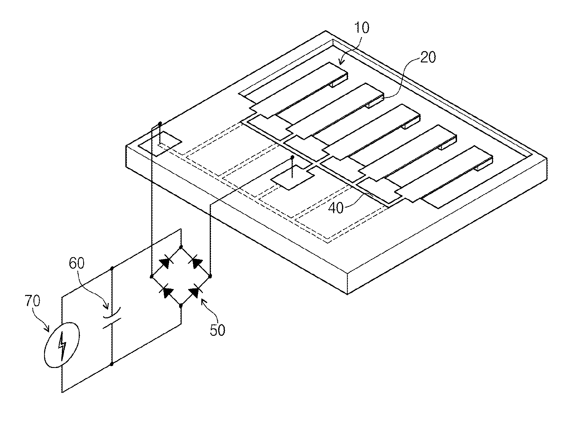
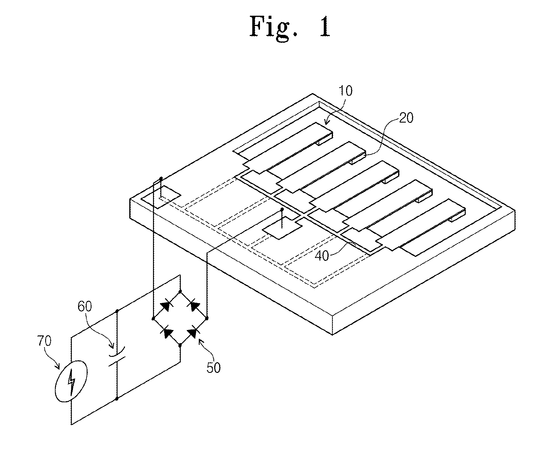
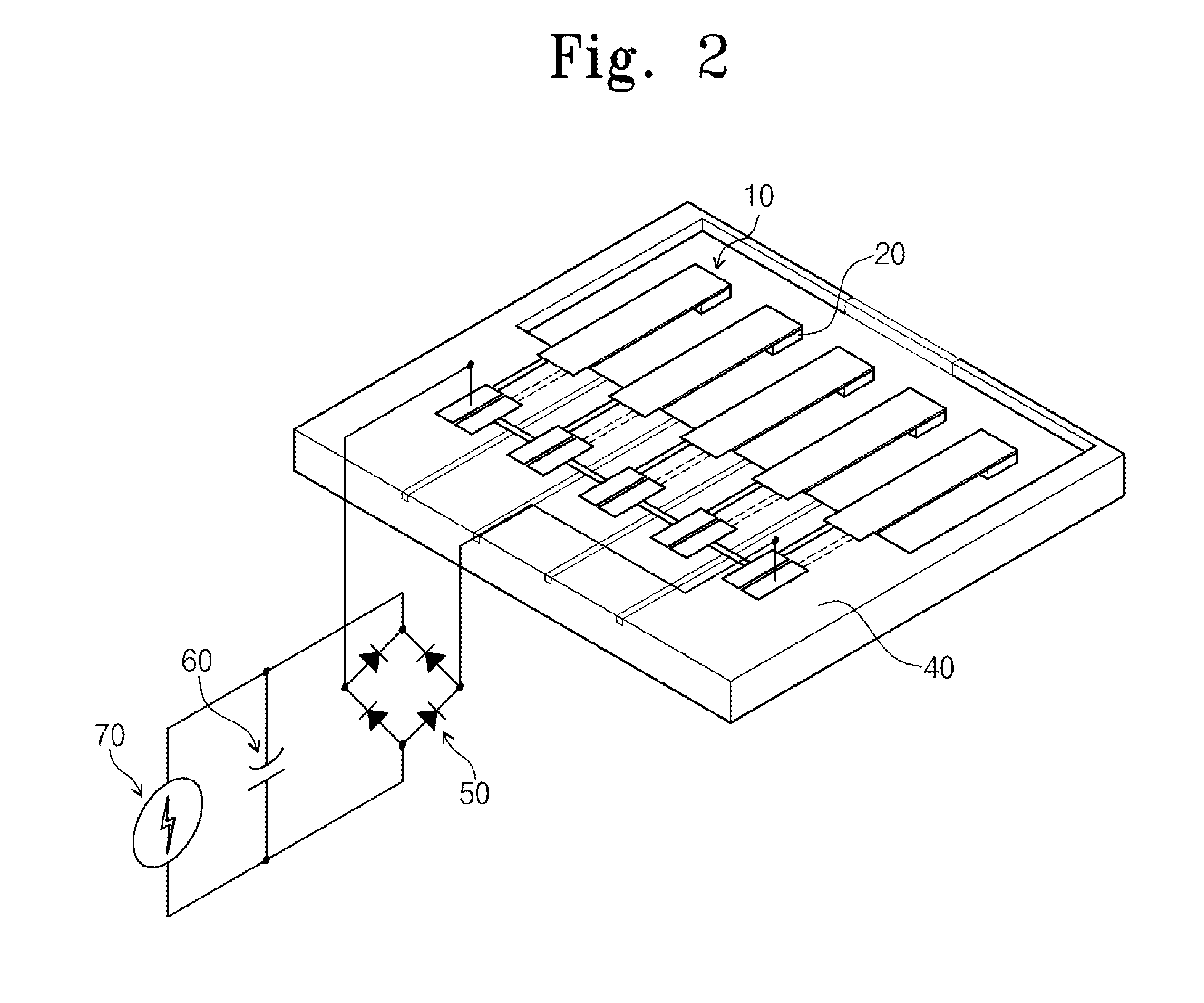
[0016]FIGS. 1 and 2 are perspective views illustrating a piezoelectric energy harvesting array in accordance with some embodiments of the inventive concept. FIG. 3 is a perspective view illustrating a piezoelectric energy harvesting device of FIGS. 1 and 2.

[0017]Referring to FIGS. 1 through 3, the piezoelectric energy harvesting array may includ...


PUM

PropertyMeasurementUnit
Weightaaaaaaaaaa
Frequencyaaaaaaaaaa
Energyaaaaaaaaaa

Abstract

The inventive concept discloses a piezoelectric energy harvesting array and a method of manufacturing the same. The manufacturing method may include forming a plurality of piezoelectric energy harvesting devices; connecting masses to one side of the piezoelectric energy harvesting devices and connecting the other side of the piezoelectric energy harvesting devices facing the masses to a base; and individually tuning a resonant frequency of each of the piezoelectric energy harvesting devices to prevent mismatch of resonant frequency when the masses vibrate.

Description

CROSS-REFERENCE TO RELATED APPLICATIONS[0001]This U.S. non-provisional patent application claims priority under 35 U.S.C. §119 of Korean Patent Application Nos. 10-2012-0056242, filed on May 25, 2012, and 10-2012-0151127, filed on Dec. 21, 2012, the entire contents of which are hereby incorporated by reference.BACKGROUND[0002]The present inventive concept herein relates to energy harvesting power supply devices, and more particularly, to a piezoelectric energy harvesting array including a plurality of piezoelectric energy harvesting devices and a method of manufacturing the same.[0003]Recently, because of the development of electrical communication technology, various kinds of electronic devices are being appeared. For example, as an electronic device such as portable electronic equipments realizes a user oriented ubiquitous computing, the demand for the portable electronic equipment is explosively being increased. Portable electronic equipments may include a portable power supply s...

Claims


Application Information

Patent Timeline
IPC IPC(8): H02N2/18H02N2/00
CPCH02N2/188H02N2/22Y10T29/42H10N30/306H10N30/80H02N2/186
Inventor LEE, SANG KYUNKIM, MOONKEUN
Owner ELECTRONICS & TELECOMM RES INST
Why Eureka
Eureka Blog
Learn More