

Displacement measurement device
- Summary
- Abstract
- Description
- Claims
- Application Information
AI Technical Summary
Benefits of technology
Problems solved by technology
Method used
Image

Examples
first embodiment
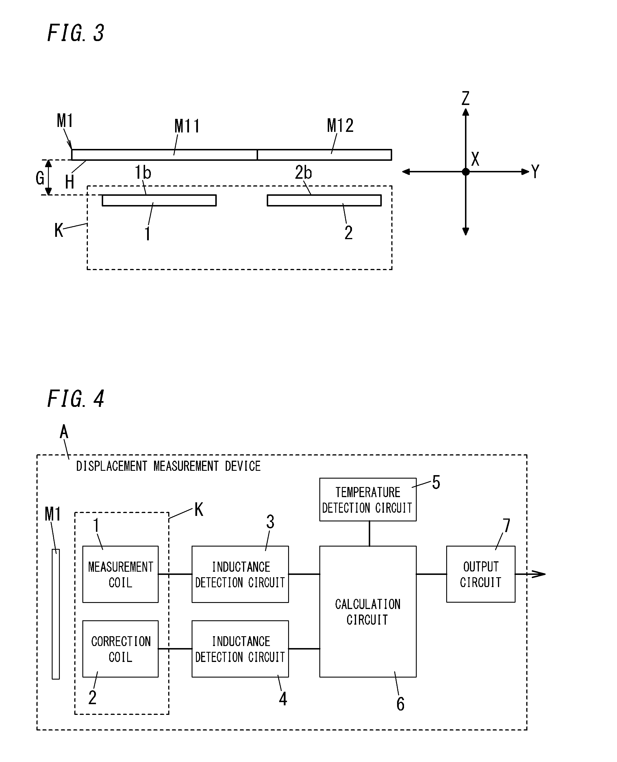
[0045]FIG. 4 shows a block configuration of the displacement measurement device A of the present embodiment.
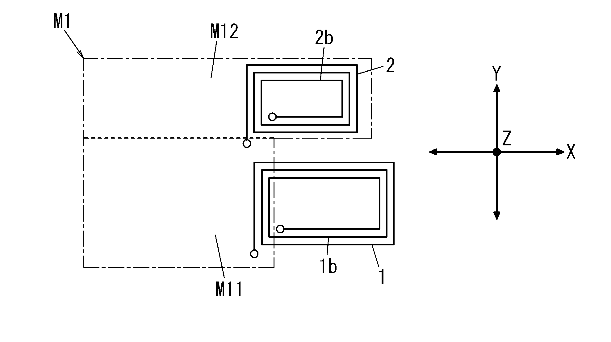
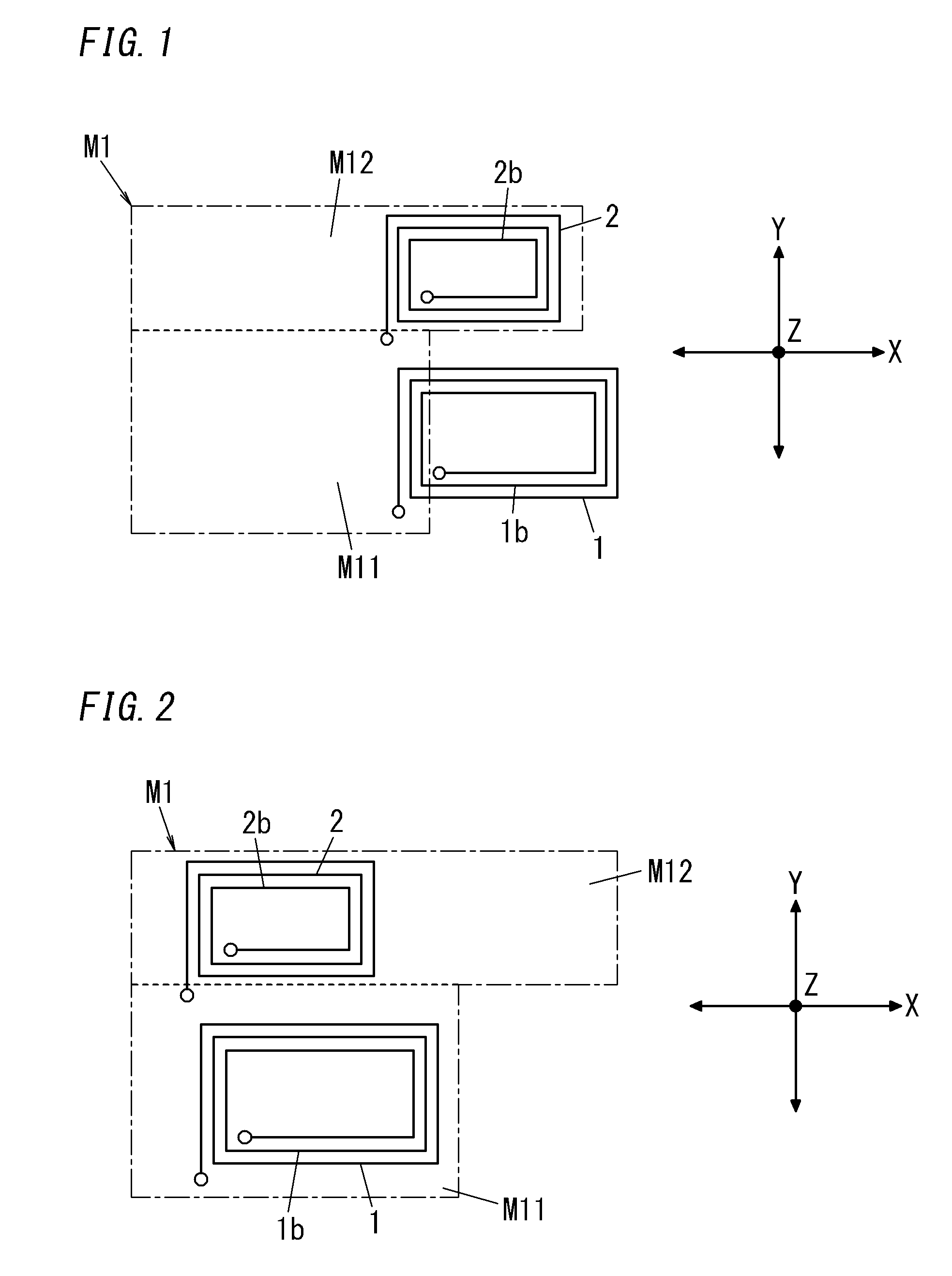
[0046]The displacement measurement device A includes a measurement coil 1, a correction coil 2, an inductance detection circuit (inductance detection circuits 3 and 4), a temperature detection circuit 5, a calculation circuit 6, an output circuit 7, and a metal object (metal member) M1. Further, the measurement coil 1 and the correction coil 2 constitute a detection unit K.
[0047]The inductance detection circuit includes the two inductance detection circuits 3 and 4. The inductance detection circuit 3 is configured to measure an inductance L1 of the measurement coil 1 and the inductance detection circuit 4 is configured to measure an inductance L2 of the correction coil 2.
[0048]The temperature detection circuit 5 is configured to measure a temperature of the detection unit K.
[0049]The calculation circuit 6 creates a displacement signal according to a relative position of the me...
second embodiment
[0094]For example, inclination of the metal object M1 is likely to cause a variation in the gap length between the metal object M1 and the correction coil 2. Hence, an error may occur in the inductance L2 of the correction coil 2.
[0095]In view of the above, as shown in FIG. 14, the displacement measurement device A of the present embodiment includes the correction coil constituted by paired correction coils 21 and 22 (first and second correction coils) connected in series with each other. In other words, the first correction coil 21 and the second correction coil 22 constitute the correction coil.
[0096]The correction coils 21 and 22 are arranged in the Y direction. The measurement coil 1 is interposed between the correction coils 21 and 22. Accordingly, the correction coil 21, the measurement coil 1, and the correction coil 22 are arranged in the Y direction in this order.
[0097]The metal object M1 is provided with a cutout at a center part opposite to the measurement coil 1 of the s...
third embodiment
[0107]For example, inclination of the metal object M1 is likely to cause a variation in the gap length between the metal object M1 and the measurement coil 1. Hence, an error may occur in the inductance L1 of the measurement coil 1.
[0108]In view of the above, as shown in FIG. 15, the displacement measurement device A of the present embodiment includes the measurement coil constituted by paired measurement coils 11 and 12 (first and second measurement coils) connected in series with each other. In other words, the first measurement coil 11 and the second measurement coil 12 constitute the measurement coil.
[0109]The measurement coils 11 and 12 are arranged in the Y direction. The correction coil 2 is interposed between the measurement coils 11 and 12. Accordingly, the measurement coil 11, the correction coil 2, and the measurement coil 12 are arranged in the Y direction in this order.
[0110]The metal object M1 is provided with a protrusion opposite to the correction coil 2 which extend...
PUM
 Abstract
Description
Claims
Application Information