
Drive assembly for an autoinjector and a method of assembling an autoinjector

a technology of autoinjector and drive assembly, which is applied in the direction of infusion syringes, other medical devices, intravenous devices, etc., can solve the problems of inability to handle drug components, inability to use, and confusion in the approach,

Active Publication Date: 2013-11-28
OVAL MEDICAL TECH
View PDF11 Cites 57 Cited by
  • Summary
  • Abstract
  • Description
  • Claims
  • Application Information

AI Technical Summary

Benefits of technology

The patent text describes a device that has a retaining means that can be connected to a coupling means. The retaining means is designed to move to a specific position when the coupling means is not engaged with a drug containing portion. This provides additional security during transit. The coupling means has a mechanism that moves during coupling to expose an aperture in which the retaining means is engaged. This allows for the use of a tool to disengage the retaining means. The technical effects of this device include increased security and ease of use.

Problems solved by technology

Some autoinjectors include a finger-operated button or other control to allow the patient to activate them, but this approach can be confusing and more difficult to use.
The device manufacturers are generally not able to handle the drug component.
Equally, the filling facilities generally lack device assembly expertise or capability.
This can be difficult and complex to achieve, and can increase the size and cost of the autoinjector.
There is a risk that energy source can be released before final assembly due to handling forces.

Method used


Image

  • Drive assembly for an autoinjector and a method of assembling an autoinjector
  • Drive assembly for an autoinjector and a method of assembling an autoinjector
  • Drive assembly for an autoinjector and a method of assembling an autoinjector

Examples


Embodiment Construction

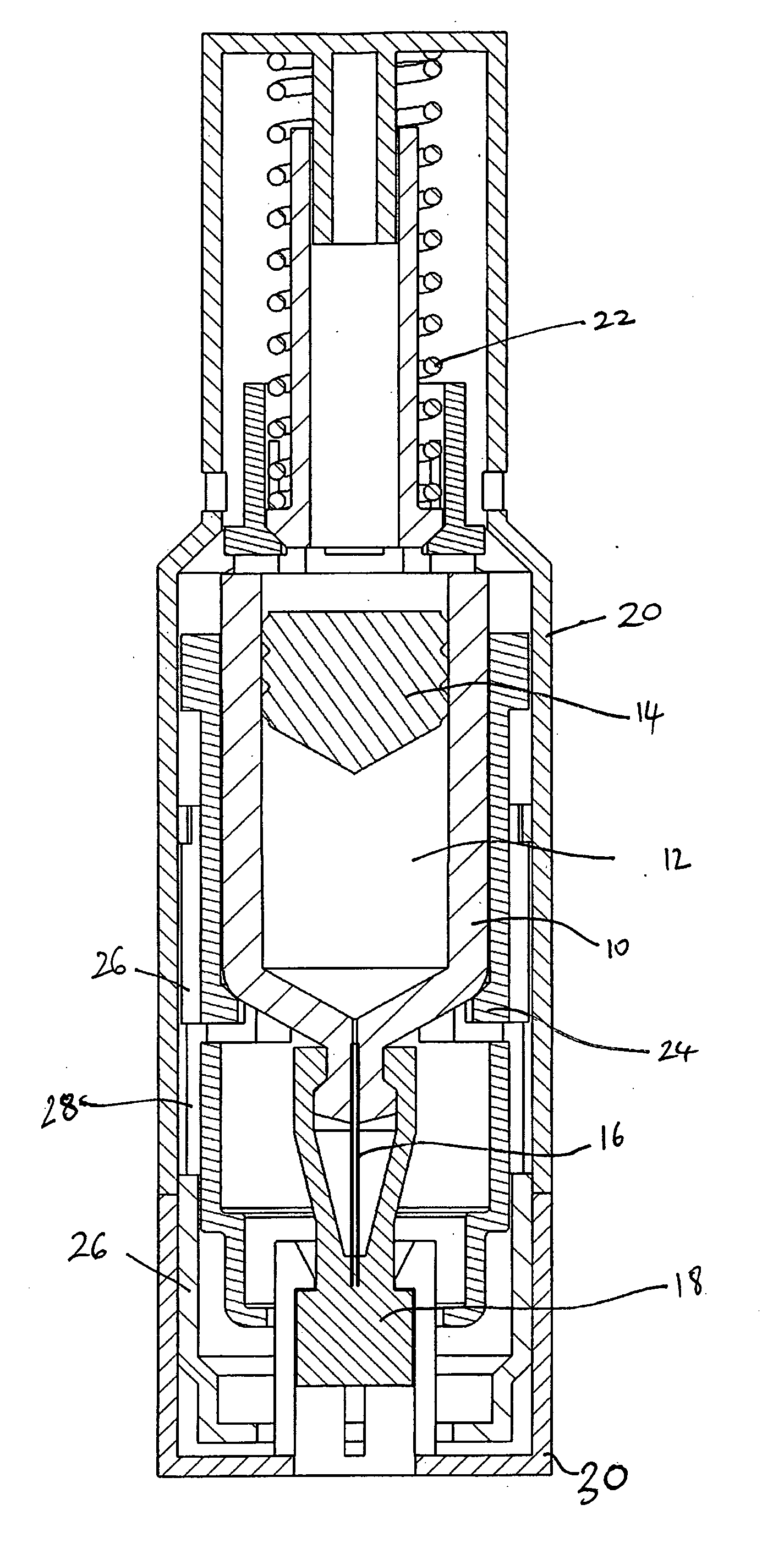
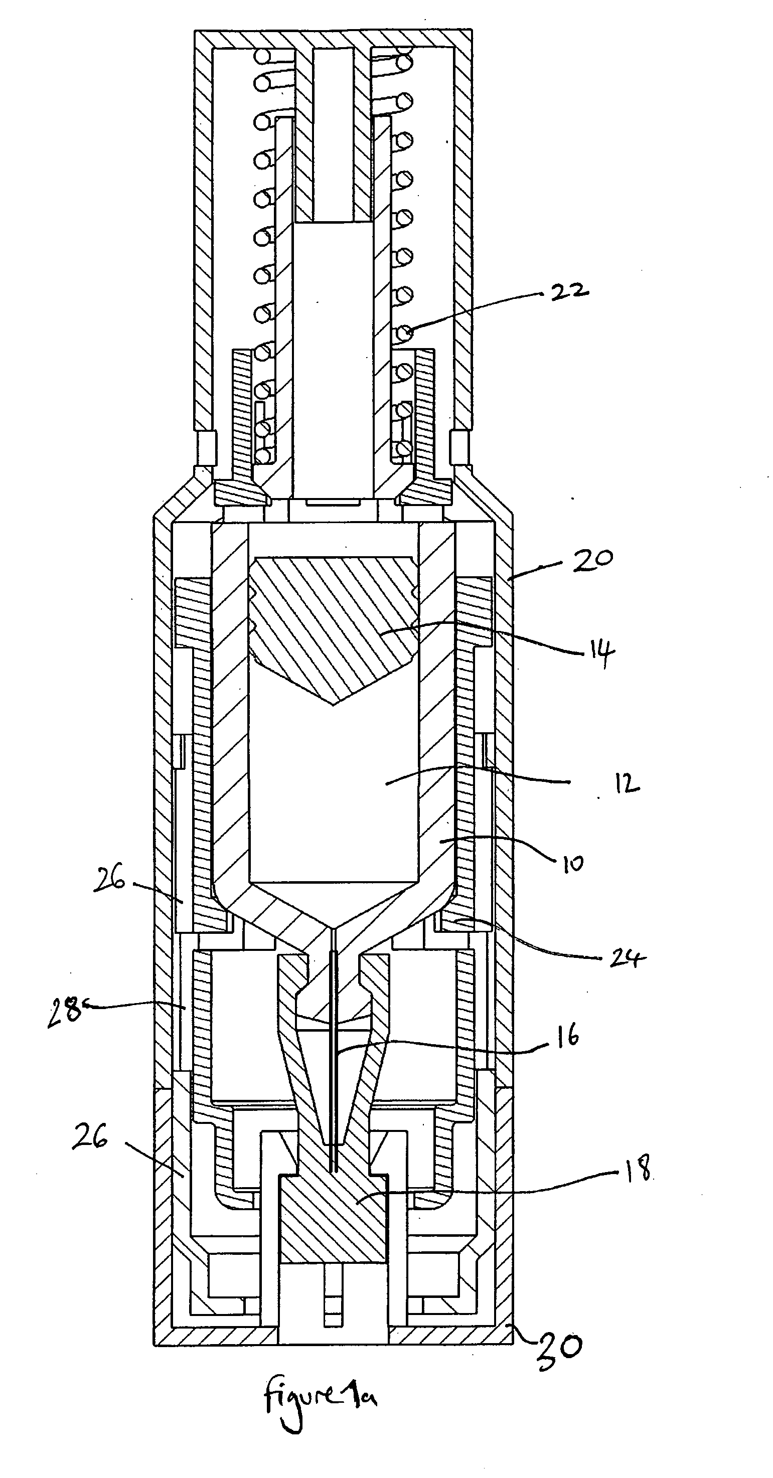
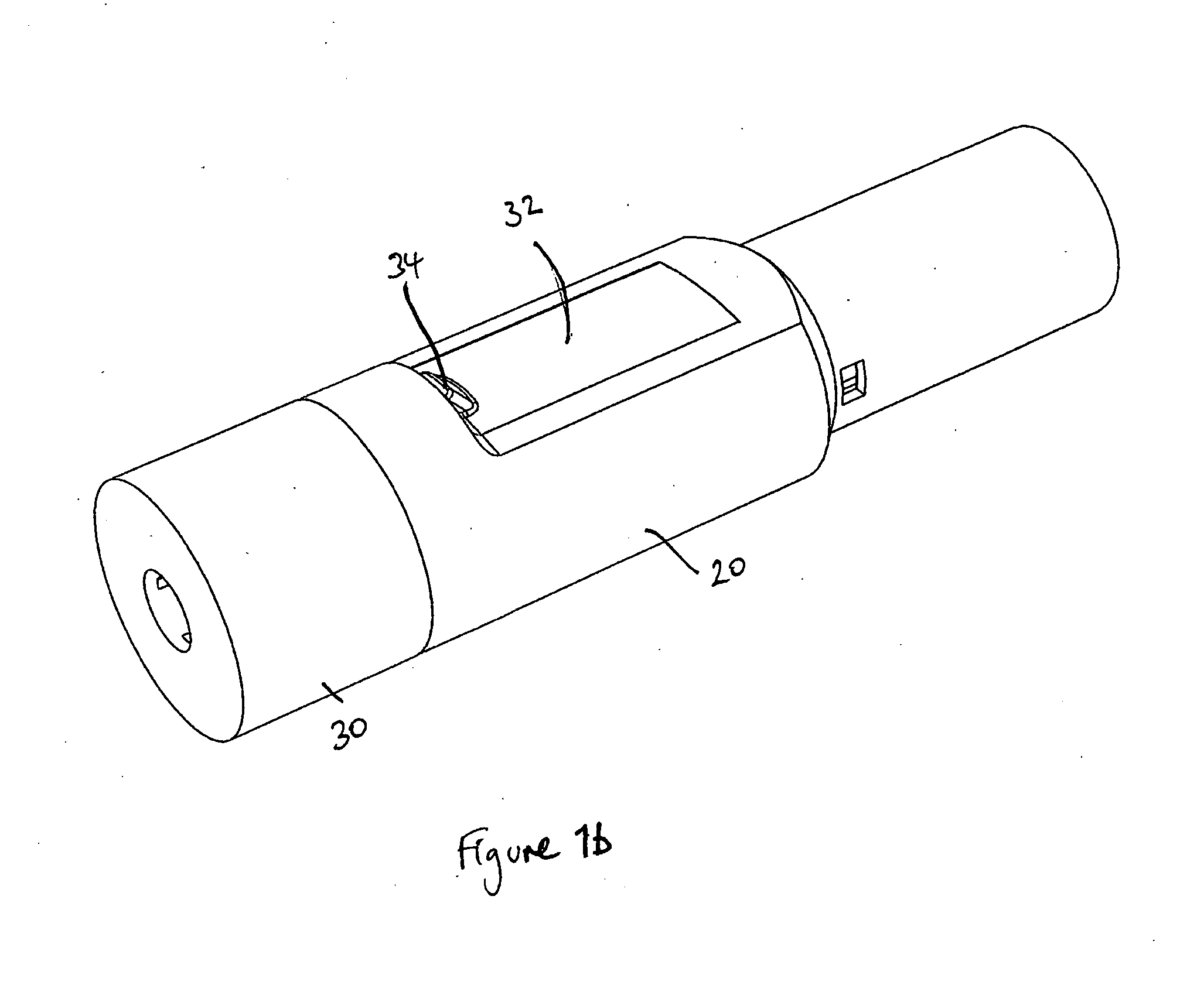
[0063]FIG. 1 is a cross section of an autoinjector in accordance with an embodiment of the invention. The autoinjector comprises a drug container 10 holding a drug 12. The drug container is closed by a plunger 14 at its rear end. In this embodiment, the drug container is formed from cyclic olefin copolymer, but it may be formed from any suitable plastics material or may be formed of glass. The plunger is formed from a rubber material, such as styrene butadiene rubber. At the front end of the drug container there is a hypodermic needle 16, which is fixed to the drug container 10 using an adhesive, or another suitable fixing mechanism. The front end of the needle 16 is embedded in a rubber sock 18, which is coupled to the drug container and completely seals the needle, keeping it sterile.

[0064]The drug container and needle assembly is held within an autoinjector housing 20. Also within the housing 20 is a drive mechanism comprising a stored energy source in the form of a helical sprin...


PUM

PropertyMeasurementUnit
Energyaaaaaaaaaa
Potential energyaaaaaaaaaa

Abstract

The invention provides a drive mechanism for an autoinjector, configured to be coupled to a drug containing portion to form a complete autoinjector, the drive mechanism comprising: a housing (20); a drive means coupled to the housing, the drive means comprising a resilient member (22); a retaining means coupled to the housing, the retaining means (60) engaging the drive means in a first position to retain the resilient member in a deformed condition, and releasing the drive means in a second position; and a coupling means (24) for coupling with a drug containing portion (10). The drug containing portion retains the drive means in a second deformed condition when the retaining means is in the second position, the drive means storing enough energy in the second deformed condition to drive needle insertion and / or drug delivery.

Description

FIELD OF THE INVENTION[0001]The present invention relates to autoinjectors and in particular to a drive assembly for an autoinjector that permits for simple assembly of an autoinjector.BACKGROUND TO THE INVENTION[0002]An autoinjector is a drug delivery device which contains a medical, therapeutic, diagnostic, pharmaceutical or cosmetic compound (drug) before it is administered, and which is used to administer the compound through the skin of the patient via a hollow needle. Autoinjectors may be used by the patient themselves or by a different user, and are also used to administer drugs to animals.[0003]Autoinjectors are typically used because they reduce the amount of training and effort needed by a user compared with that needed for a syringe, by automating either or both processes of inserting the needle into the patient and expelling the drug through the needle. They can also reduce the fear of injection by hiding the needle from the patient[0004]Autoinjectors typically include a...

Claims


Application Information

Patent Timeline
IPC IPC(8): A61M5/20
CPCA61M5/2033A61M5/3204A61M2005/2013A61M2005/2073Y10T29/53
Inventor REBER, DOMINIC CHARLESHUANG, CONGYIYOUNG, MATTHEW
Owner OVAL MEDICAL TECH
Learn More