Dual circuit pneumatic foot valve with electronically controlled proportional modulator (ECPM) and operator input sensing

Active Publication Date: 2013-12-05
BENDIX COMML VEHICLE SYST LLC
View PDF5 Cites 31 Cited by
  • Summary
  • Abstract
  • Description
  • Claims
  • Application Information

AI Technical Summary

Benefits of technology

[0012]In one aspect, a foot control valve assembly for operating a vehicle brake system having an associated brake pedal and at least one braking circuit associated with one or more wheels of the vehicle, the valve assembly comprising a brake valve for selectively applying braking pressure to the at least one braking circuit of the vehicle, the brake valve being proportionally actuatable by a vehicle operator via a plunger operatively connectable to the associated brake pedal, a brake valve actuator for selectively actuating the brake valve to effect an autonomous braking function, the brake valve actuator responsive to a pneumatic control signal, an electronically controlled proportional modulator responsive to an electronic control signal received from an associated controller, the electronically controlled proportional modulator configured to modulate the pneumatic control signal provided to the brake valve actuator to control actuation of the at least one brake valve during an autonomous braking event, and at least one sensor for sensing driver braking demand, the sensor configured to communicate sensed driver braking demand to the associated controller.
[0013]The plunger can be actuated via the associated brake pedal to operate the brake valve to deliver pressure to the braking circuit regardless of the state of the electronically controlled proportional modulator. A first end of the plunger can be adapted for connection to the associated

Problems solved by technology

That is, since the modulators for the non-driven wheels can hold, and not allow any new pressure to go to their associated brakes, the system can supply fu

Method used


Image

  • Dual circuit pneumatic foot valve with electronically controlled proportional modulator (ECPM) and operator input sensing
  • Dual circuit pneumatic foot valve with electronically controlled proportional modulator (ECPM) and operator input sensing
  • Dual circuit pneumatic foot valve with electronically controlled proportional modulator (ECPM) and operator input sensing

Examples


Embodiment Construction

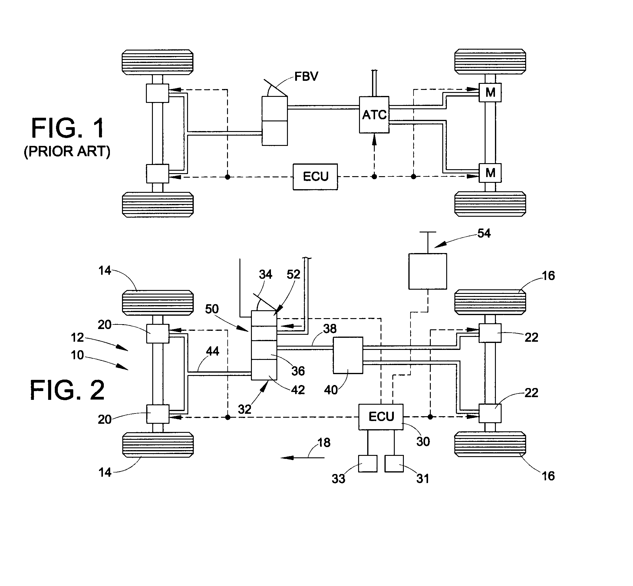
[0024]The present disclosure relates to a braking system for a vehicle. In particular, the present disclosure relates to a vehicle braking system that provides, for example, an automatic traction control (ATC) function, RSC, ASB, AEB and / or other automated braking functions. The invention is applicable to braking systems of differing constructions. For example, the invention is applicable to braking systems for vehicles having only two axles, with either one or both axles being driven, as well as vehicles having more than two axles with one or more being driven, and also vehicles (such as trailers) having no driven axles.

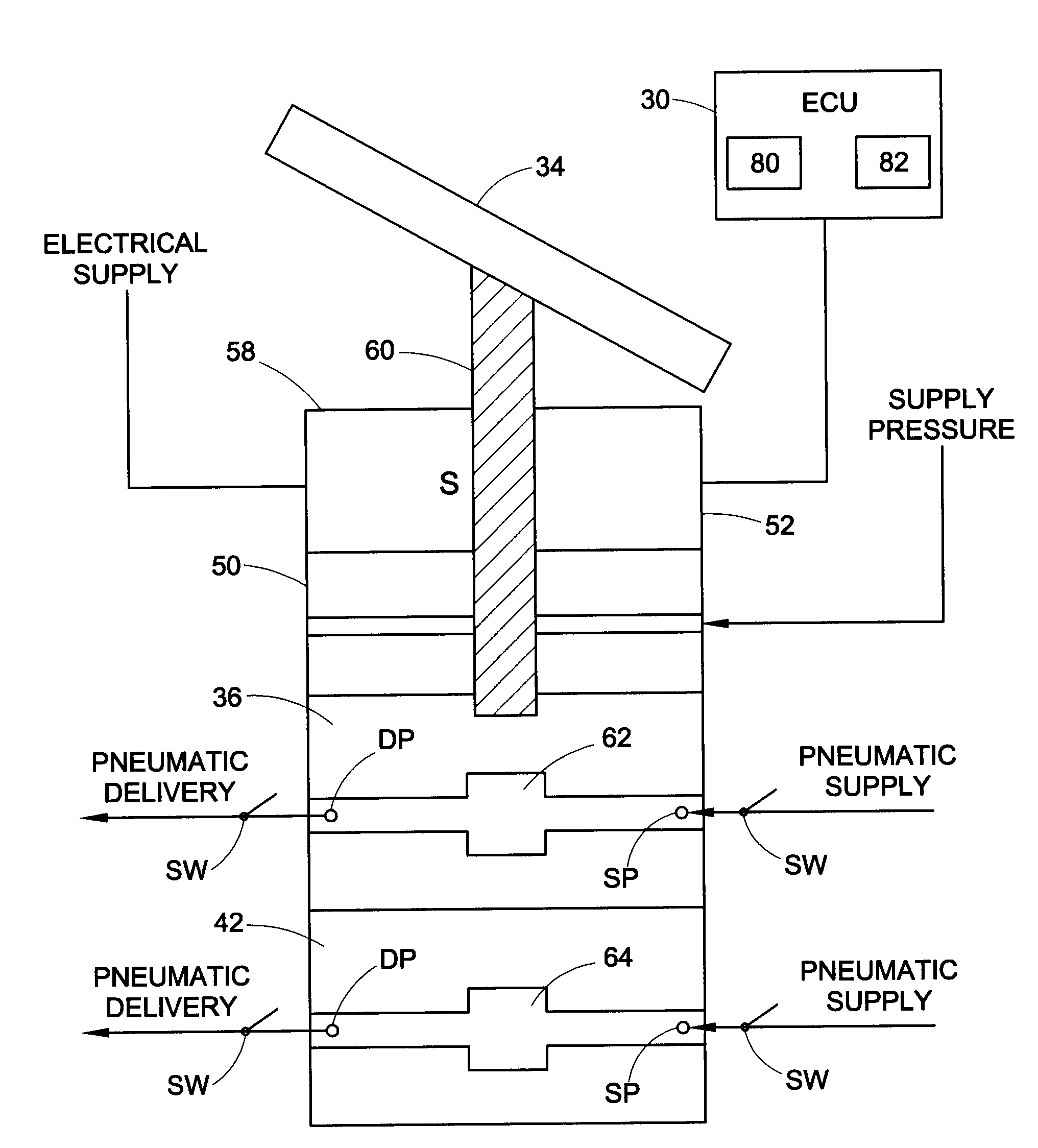
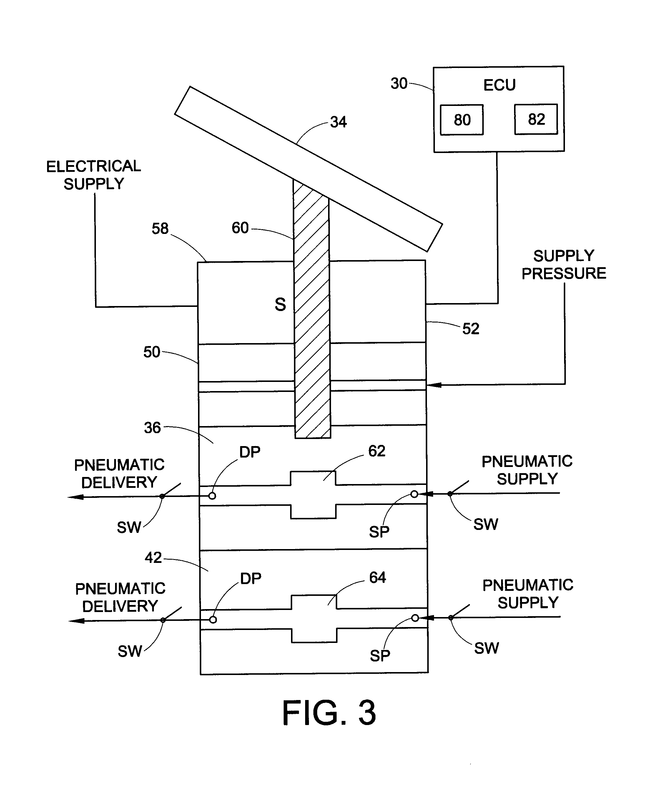
[0025]Many electronically controlled safety systems must apply the service brakes autonomously to correct for certain impending situations. Often it is also necessary to have an operator input auxiliary braking means. These systems can include ESP, RSC, ACB, AEB, ATC, work brakes, service-door interlock system, etc. Current methodologies generally require multiple a...


PUM


Abstract

A foot valve that can be activated either by the driver or an electronic control unit, wherein the foot valve can be the central driving device for automated braking applications such as Hill Start Aid and Work Brake Systems. Pneumatic pressure delivered by an electronically controlled proportional modulator to the foot valve activates either primary and/or secondary portions of the brake valve. The driver can mechanically override the electronic intervention when he presses on the brake pedal. For applications such as ESC and ATC, driver demand can be sensed by sensors in the foot valve and transmitted to the braking system electronic controller on the vehicle.

Description

BACKGROUND[0001]The present exemplary embodiment relates to a braking system for a vehicle. It finds particular application in conjunction with a foot valve for a braking system, and will be described with particular reference thereto. However, it is to be appreciated that the present exemplary embodiment is also amenable to other like applications.[0002]A typical vehicle braking system for a straight truck, bus, tractor, or trailer, includes a source of pressurized air along with valves for selectively directing the air to brake chambers at the wheels of the vehicle. Vehicle air brake systems typically include a primary circuit, which is often used for driven wheels, and a secondary circuit, which is often used for non-driven wheels. The vehicle has a dual brake valve, or foot brake valve (FBV), which is a valve in both the primary circuit and the secondary circuit that is controlled by the foot pedal (brake pedal) of the vehicle in response to driver demand for braking. The dual b...

Claims


Application Information

Patent Timeline
IPC IPC(8): B60T13/58B60T7/12B60T7/04B60T13/68
CPCB60T7/042B60T13/662B60T13/683
Inventor EBERLING, CHARLES E.BENNETT, MARK A.
Owner BENDIX COMML VEHICLE SYST LLC
Why Eureka
Try Eureka