Method for reducing hot spots in a light guide plate utilizing a reversed micro-pattern in its mixing zone

Inactive Publication Date: 2013-12-12
SKC HAAS DISPLAY FILMS CO LTD
View PDF3 Cites 4 Cited by
  • Summary
  • Abstract
  • Description
  • Claims
  • Application Information

AI Technical Summary

Benefits of technology

[0005]The present invention provides a method of reducing hot spots in a light guide plate, the light guide plate comprising an input surface for receiving light from a plurality of discrete light sources, an output surface for emitting light, a bottom surface opposing to the output surface, and an end surface opposing to the input surface, wherein the direction from the input surface to the end surface is defined as Y-axis, the direction that is perpendicular to the Y-axis and parallel to the discrete light sources is defined as X-axis, the output surface has a plurality of elongated grooves running parallel to the Y-axis and extending from the input surface corresponding to Y=0 to the end surface, the bottom surface has a core zone ex

Problems solved by technology

Subsequently, the pitch of the LEDs has become larger, which results in a more noticeable hot spot problem, that is, more light is distributed near each LED than between LEDs in the first few millimeters of the viewing area of the LCD.
The hot spot problem occurs because light from the discret

Method used


Image

  • Method for reducing hot spots in a light guide plate utilizing a reversed micro-pattern in its mixing zone
  • Method for reducing hot spots in a light guide plate utilizing a reversed micro-pattern in its mixing zone
  • Method for reducing hot spots in a light guide plate utilizing a reversed micro-pattern in its mixing zone

Examples


Embodiment Construction

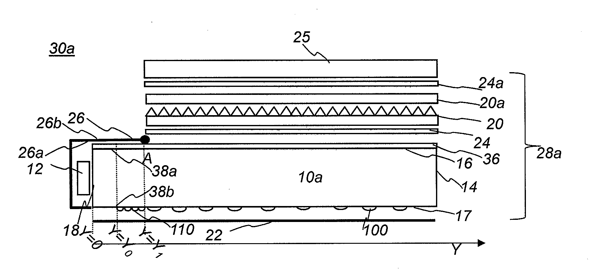
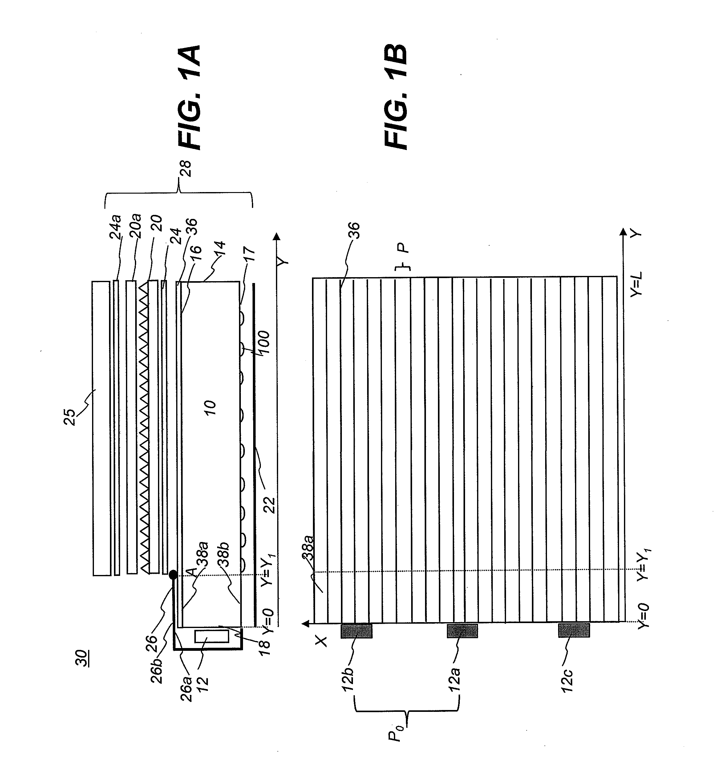
[0020]FIG. 1A shows schematically a side view of an LCD display apparatus 30 comprising an LCD panel 25 and a backlight unit 28. Backlight unit 28 comprises a plurality of optical components including one or two prismatic films 20, 20a, one or two diffusive films 24, 24a, a bottom reflective film 22, a top reflective component 26, and a light guide plate (LGP) 10. LGP 10 is different from the other optical components in that it receives the light emitted from one or more light sources 12 through its input surface 18, redirects the light emitted through its bottom surface 17, end surface 14, output surface 16, side surfaces 15a, 15b (not shown) and reflective film 22, and eventually provides light relatively uniform to the other optical components. Output surface 16 has a plurality of elongated grooves 36. Target luminance uniformity is achieved by controlling the density, size, and / or orientation of the lenses 100 (sometimes referred to as discrete elements, or light extractors) on ...


PUM


Abstract

The present invention provides a method of reducing hot spots in a light guide plate. The method comprises distributing a set of lenses in the core zone and a set of micro-lenses in the mixing zone between Y=Y0 and Y=Y1, wherein the density of the set of micro-lenses varies in the X-axis, having a maximum value at a first location that has a same X value as the center of one of the discrete light sources, and having a minimum value at a second location that has a same X value as the center of two adjacent discrete light sources, and a size and density of the micro-lenses is selected to redirect the light from the discrete light sources toward the Y-axis and provide a ratio L1/L0 that is between 0.9 and 1.1 for any Y≧Y1.

Description

FIELD OF THE INVENTION[0001]This invention generally relates to a light guide plate, and more particularly, to a light guide plate having a reversed, one or two dimensional micro-pattern in its mixing zone to reduce undesirable hot spot defects caused by discrete light sources.BACKGROUND OF THE INVENTION[0002]Liquid crystal displays (LCDs) continue to improve in cost and performance, becoming a preferred display type for many computer, instrumentation, and entertainment applications. Typical LCD-based mobile phones, notebooks, and monitors include a light guide plate (LGP) for receiving light from a light source and redistributing the light uniformly across the light output surface of the LGP. The light source, conventionally being a long, linear cold-cathode fluorescent lamp, has evolved to a plurality of discrete light sources such as light emitting diodes (LEDs). For a given size LCD, the number of LEDs has been steadily decreasing to reduce cost. Subsequently, the pitch of the L...

Claims


Application Information

Patent Timeline
IPC IPC(8): F21V8/00
CPCG02B6/0036G02B6/0038G02B6/0043G02B6/0068G02B6/10G02F1/1335
Inventor MI, XIANG-DONG
Owner SKC HAAS DISPLAY FILMS CO LTD
Why Eureka
Try Eureka