Method and apparatus for optical delivery fiber having cladding with absorbing regions

a technology of optical delivery fiber and absorbing region, which is applied in the direction of cladded optical fibre, instruments, optical elements, etc., can solve the problems of catastrophic changes in operating performance, unreliable devices that fail, etc., and achieve the effects of reducing hot spots, increasing length, and reducing concentration

Active Publication Date: 2007-10-04
LOCKHEED MARTIN CORP
View PDF23 Cites 31 Cited by
  • Summary
  • Abstract
  • Description
  • Claims
  • Application Information

AI Technical Summary

Benefits of technology

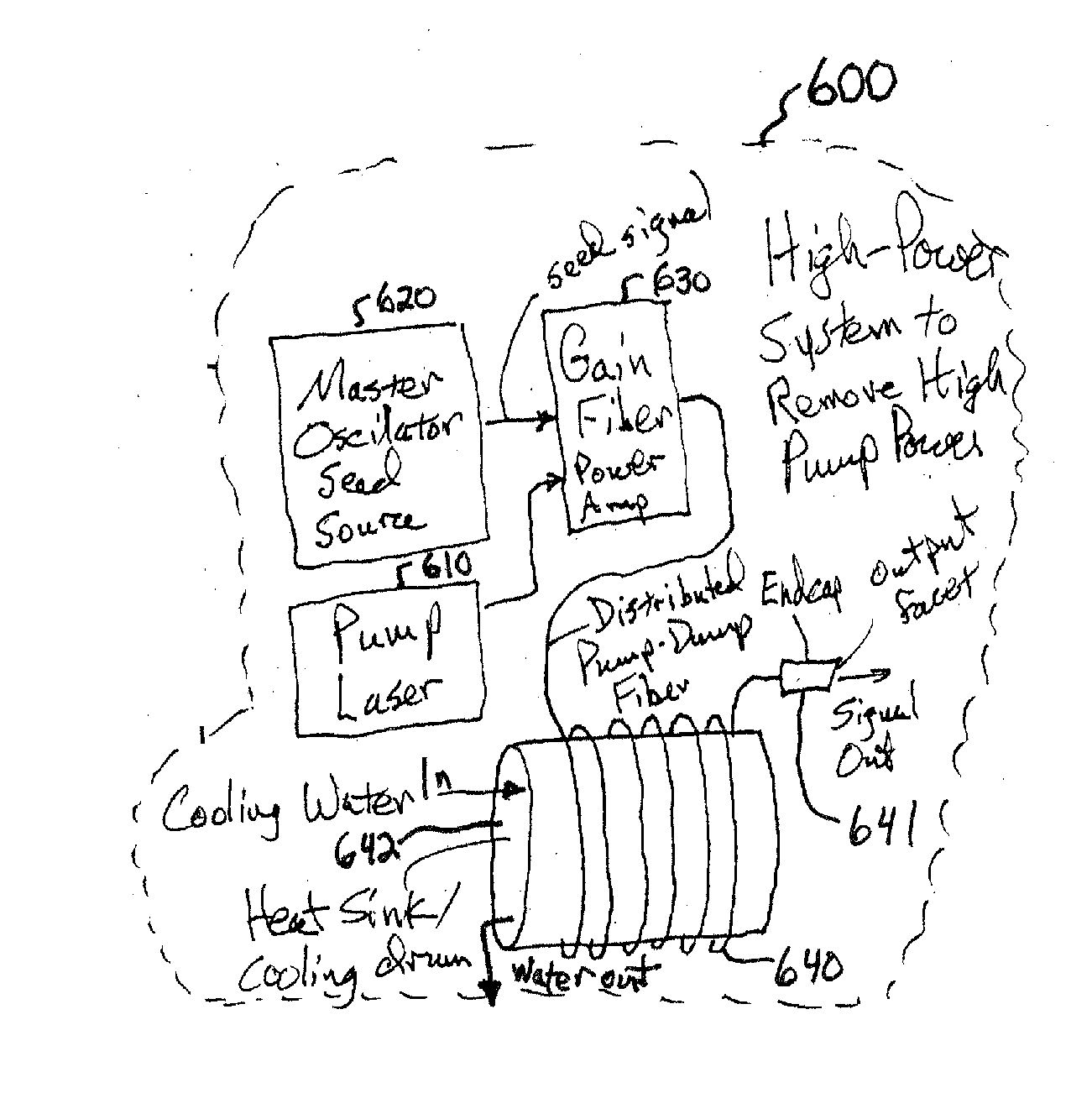
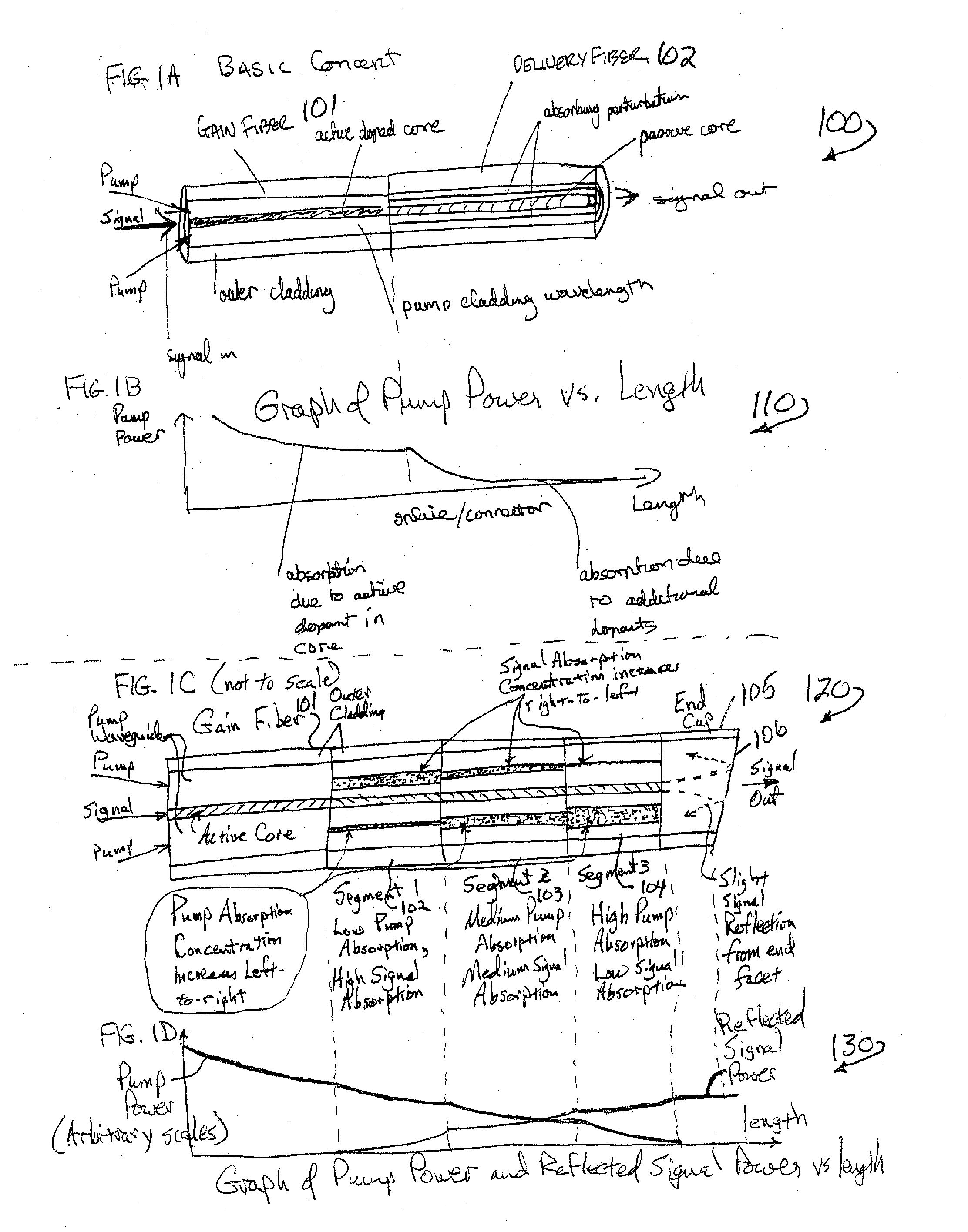
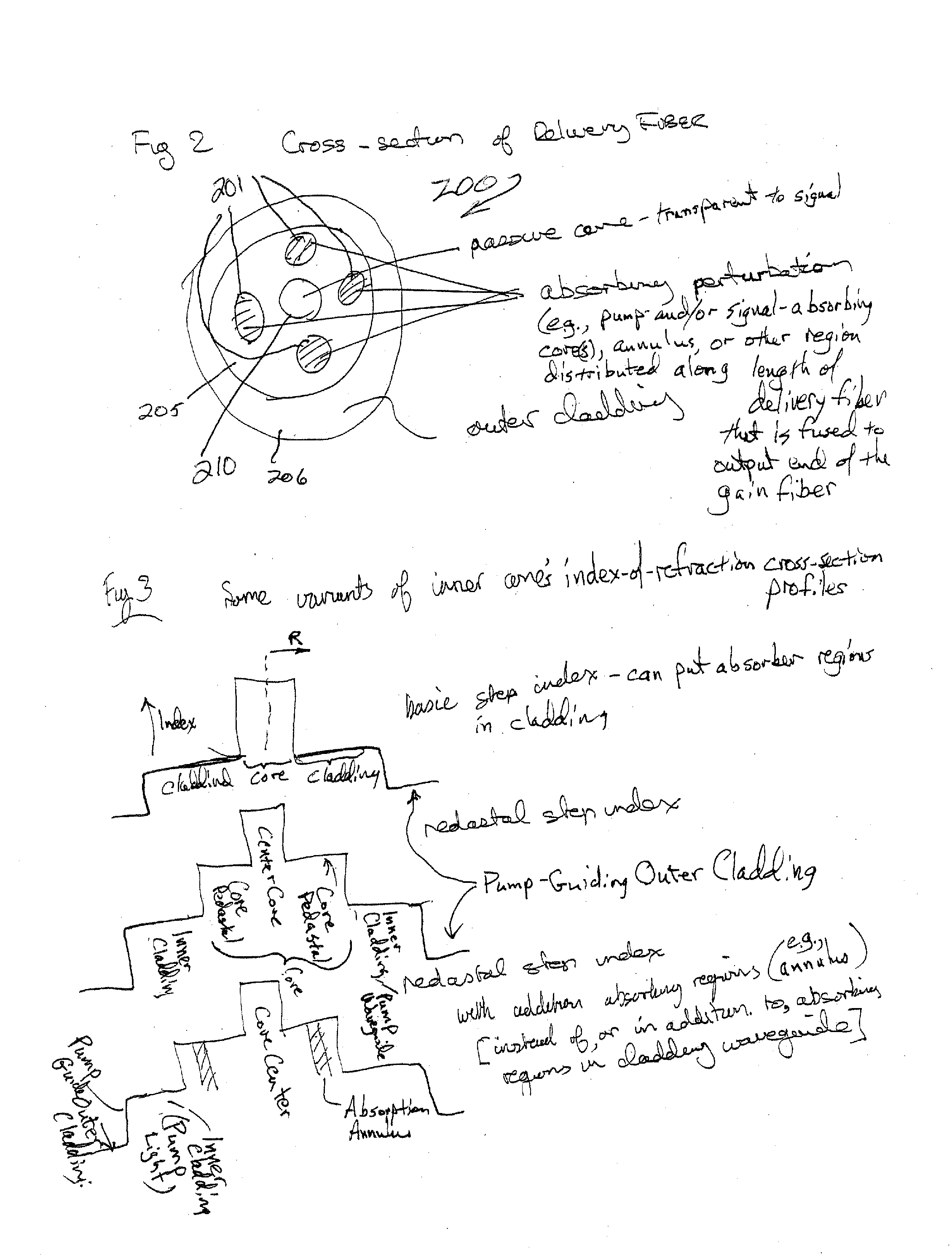
[0012] Accordingly, some embodiments of the present invention provide a delivery fiber with a distributed absorbing region between the end of the output amplifying fiber and the location where the signal light is delivered. In some embodiments, the absorbing region is doped with one or more elements (e.g., cobalt, thulium, or some other metal or rare-earth element) selected for their ability to absorb the pump and / or signal wavelengths and as a result, to heat up, or in some cases to re-radiate fluorescence isotropically. The distributed absorbing region not only absorbs a desired amount of the pump and / or signal light (converting the light's energy into heat or fluorescence), but also spreads the energy dissipation over an extended region, thus reducing hot spots that would lead to device failure. In some embodiments, the distributed pump-dump delivery fiber uses a reduced concentration of the absorbing material and an increased length, in order to reduce the amount of absorbed power per unit length and further spread the heat. In some embodiments, the concentration of absorbing material is low at the end of the distributed pump-dump delivery fiber that is fused to the amplifying fiber, and the concentration of absorbing material gradually increases towards its opposite delivery end. In some embodiments, a plurality of distributed pump-dump delivery fiber sections as spliced together, wherein a first section having a low concentration of absorbing material is fused to the amplifying fiber, and successive sections have higher concentrations of absorbing material until a last absorbing section having the highest concentration of absorbing material. In some embodiments, an endcap having no core is spliced to the end of the delivery fiber, in order that the very-high-power signal light disperses at least somewhat before it encounters the end facet, in order to increase the beam diameter and reduce the power concentration of the signal beam at the output facet (thus reducing the danger of optical damage to the output facet.

Problems solved by technology

If all this pump power is dumped in one small place (e.g., at a splice between the amplifying fiber and a passive delivery fiber) a hot spot will result, leading to unreliable devices that fail (have catastrophic changes in operating performance).

Method used


Image

  • Method and apparatus for optical delivery fiber having cladding with absorbing regions
  • Method and apparatus for optical delivery fiber having cladding with absorbing regions
  • Method and apparatus for optical delivery fiber having cladding with absorbing regions

Examples


Embodiment Construction

[0023] Although the following detailed description contains many specifics for the purpose of illustration, a person of ordinary skill in the art will appreciate that many variations and alterations to the following details are within the scope of the invention. Accordingly, the following preferred embodiments of the invention are set forth without any loss of generality to, and without imposing limitations upon the claimed invention.

[0024] In the following detailed description of the preferred embodiments, reference is made to the accompanying drawings that form a part hereof, and in which are shown by way of illustration specific embodiments in which the invention may be practiced. It is understood that other embodiments may be utilized and structural changes may be made without departing from the scope of the present invention.

[0025] The leading digit(s) of reference numbers appearing in the Figures generally corresponds to the Figure number in which that component is first int...


PUM


Abstract

Apparatus and method for distributed absorption of pump light over a length of delivery fiber that is, for example in some embodiments, fusion spliced to an end of a multiply clad gain fiber that has significant unused pump light at the end of the gain fiber. In some embodiments, this includes coupling a fiber amplifier to a passive-core delivery fiber that includes a distributed pump dump. In some embodiments, at an output end of the amplifying fiber there is still a significant amount of pump power. If all this pump power is dumped in one small place (e.g., at a splice between the amplifying fiber and a passive delivery fiber) a hot spot will result, leading to unreliable devices that fail (have catastrophic changes in operating performance). The present invention provides a distributed pump dump built into a delivery fiber that is passive to the signal in its core.

Description

CROSS-REFERENCE TO RELATED APPLICATIONS [0001] This claims priority to U.S. Provisional Patent Application 60 / 743,626 filed on Mar. 21, 2006, titled “METHOD AND APPARATUS FOR OPTICAL DELIVERY FIBER HAVING CLADDING WITH ABSORBING REGIONS”, which is hereby incorporated by reference in its entirety. This invention is related to U.S. Provisional Patent Application 60 / 693,579 filed on Jun. 24, 2005, titled “APPARATUS AND METHOD FOR A HIGH-GAIN DOUBLE-CLAD AMPLIFIER”, U.S. patent application Ser. No. 11 / 426,302 filed on Jun. 23, 2006, titled “APPARATUS AND METHOD FOR A HIGH-GAIN DOUBLE-CLAD AMPLIFIER”, U.S. patent application Ser. No. 11 / 567,740 titled “APPARATUS AND METHOD FOR AN ERBIUM-DOPED FIBER FOR HIGH-PEAK-POWER APPLICATIONS” filed Dec. 7, 2006, and U.S. patent application Ser. No. 11 / 420,729 titled “FIBER- OR ROD-BASED OPTICAL SOURCE FEATURING A LARGE-CORE, RARE-EARTH-DOPED PHOTONIC-CRYSTAL DEVICE FOR GENERATION OF HIGH-POWER PULSED RADIATION AND METHOD” filed May 26, 2006, which ...

Claims


Application Information

Patent Timeline
Patent Type & Authority Applications(United States)
IPC IPC(8): G02B6/032G02B6/02
CPCG02B6/02052G02B6/03638G02B6/03644G02B6/03661H01S3/094019H01S3/06729H01S3/06779H01S3/094007G02B6/266
Inventor MINELLY, JOHN D.HENRIE, JASON D.
Owner LOCKHEED MARTIN CORP
Why Eureka
Try Eureka