Downhole gas generator

a gas generator and downhole technology, applied in the direction of steam generation using hot heat carriers, insulation, borehole/well accessories, etc., can solve the problems of prior art systems struggling to cope with significant heat from combustion, and achieve the effect of reducing hot spots and/or thermal instabilities

Active Publication Date: 2014-02-06
KREIS SYNGAS
View PDF0 Cites 1 Cited by
  • Summary
  • Abstract
  • Description
  • Claims
  • Application Information

AI Technical Summary

Benefits of technology

[0018]A further objective is to provide a gas generator having individually controlled annular cooling jacket segments for the purpose of reducing hot spots and / or thermal instabilities in the combustion chamber.

Problems solved by technology

Secondly, both hot combustion gases and steam are conducted from the borehole back to the water and fuel supply.
The prior art systems struggle, however, to cope with the significant heat of combustion, particularly in the confined space of the borehole.
The prior art does not teach a plurality of independently controlled cooling jacket segments around a combustion chamber housing, with each annular cooling jacket segment being individually controlled so that an optimum mass of water flows into and out of the segment, thereby preventing the formation of hot spots in the combustion chamber housing.

Method used


Image

  • Downhole gas generator
  • Downhole gas generator
  • Downhole gas generator

Examples


Embodiment Construction

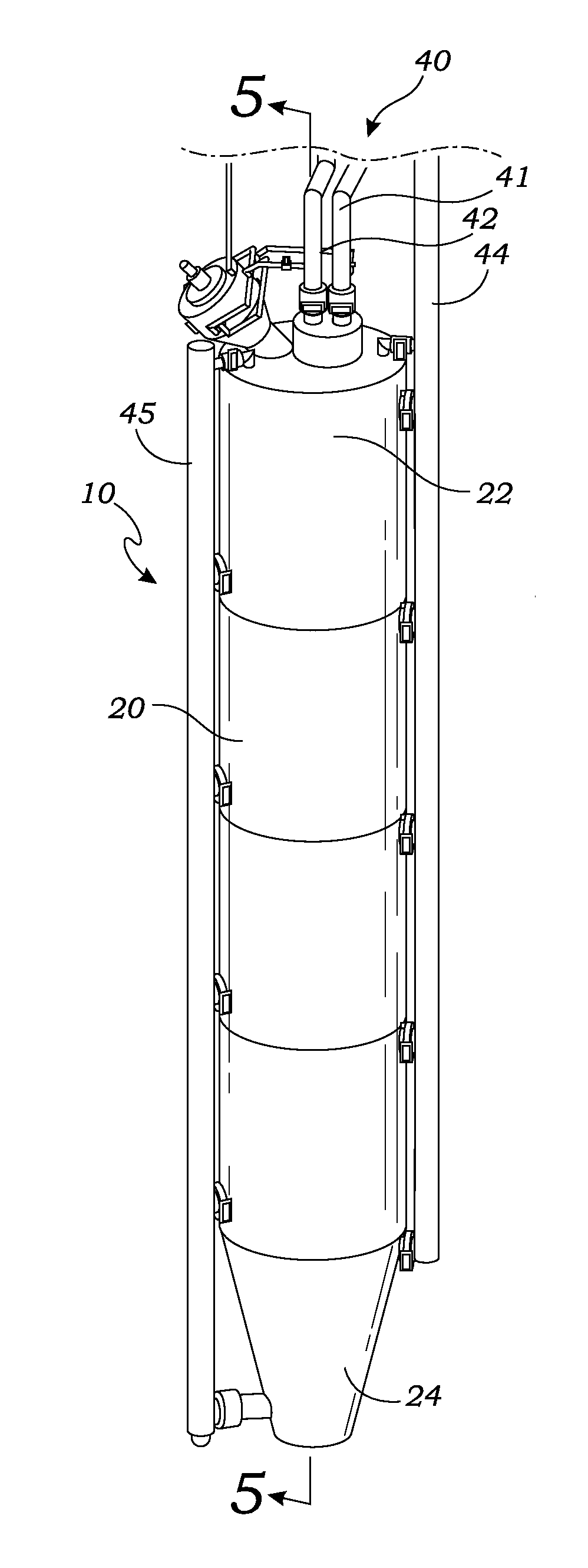
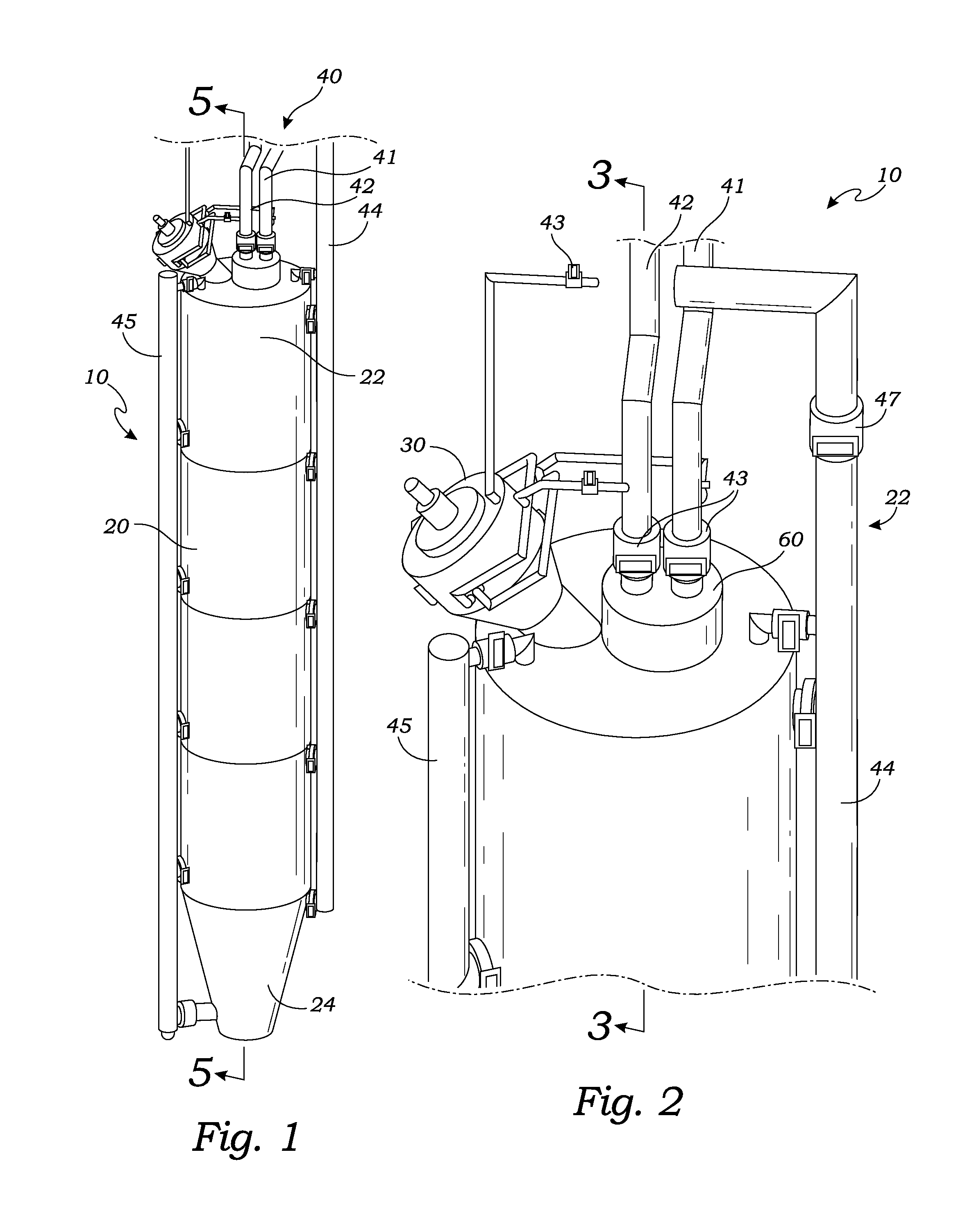
[0037]The above-described drawing figures illustrate the invention, a gas generator 10 for extracting petroleum products present in an underground reservoir. The gas generator 10 enables a method of recovering petroleum products that provides advantages over the prior art. The gas generator 10 utilizes a method for cooling the gas generator 10 that prevents the formation of hot-spots which can lead to failure of the gas generator 10.

[0038]FIG. 1 is a perspective view of one embodiment of a gas generator 10. As shown in FIG. 1, the gas generator 10 includes a combustion housing 20 for containing a combustion process which makes high-pressure steam for injection into the reservoir. The combustion housing 20 may be an elongate combustion housing 20. The elongate combustion housing 20 includes a combustion end 22 and an exhaust end 24, which are described in greater detail below. The gas generator 10 burns a fuel and an oxidizing agent to produce the high pressure gasses that are used t...


PUM


Abstract

A gas generator has an elongate combustion housing shaped to fit within a borehole for generating gasses in the borehole for use in the recovery of petroleum products. The gas generator includes a plurality of annular cooling jacket segments that surround the elongate combustion housing, each of the annular cooling jacket segments having an inlet port and an outlet port for allowing water to flow therethrough. A plurality of apertures through the elongate combustion housing allow water to flow from the plurality of annular cooling jacket segments into the elongate combustion chamber.

Description

CROSS-REFERENCE TO RELATED APPLICATIONS[0001]This application is a continuation of a previously filed utility patent, currently pending, having the application Ser. No. 14 / 016,765 filed Sep. 3, 2013, which is a continuation-in-part of application Ser. No. 13 / 942,235, filed Jul. 15, 2013, which is also currently pending.[0002]This application also claims the benefit of U.S. Provisional Application No. 61 / 679,434, filed Aug. 3, 2012.BACKGROUND OF THE INVENTION[0003]1. Field of the Invention[0004]This invention relates generally to downhole gas generators, and more particularly to a downhole gas generator having a plurality of independently controlled cooling jackets for superior cooling of the generator.[0005]2. Description of Related Art[0006]The following art defines the present state of this field:[0007]Tilmont et al., U.S. Pat. No. 8,387,692, teaches a downhole steam generation apparatus that includes an injection section, a combustion section, and an evaporation section. The inje...

Claims


Application Information

Patent Timeline
Patent Type & Authority Applications(United States)
IPC IPC(8): E21B43/243
CPCE21B43/243E21B43/24F22B1/003F22B1/18E21B36/02F02C7/12
Inventor MCGUFFIN, ROM
Owner KREIS SYNGAS
Why Eureka
Try Eureka