Turbine exhaust duct design for air cooled condensers

a turbine and exhaust duct technology, applied in the field of air cooled condensers, can solve the problems of high installation cost, high installation cost, and difficult welding of the t-piece of the steam turbine exhaust duct, and achieve the effects of improving the overall efficiency of the steam cycle plant heat rate, and reducing the steam-side pressure drop

Active Publication Date: 2013-12-19
EVAPCO
View PDF2 Cites 9 Cited by
  • Summary
  • Abstract
  • Description
  • Claims
  • Application Information

AI Technical Summary

Benefits of technology

[0006]According to the present invention, there is presented a change in the design of the ACC which would result in substantially less field welding, making ACCs having this design much more attractive to purchase and erect.
[0021]According to another aspect of the invention, there is provided a method for facilitating de-aeration of a steam condensate, reducing corrosion in the steam cycle and for increasing the life of a power plant, the method comprising delivery of spent plant steam to an ACC via an inline V turbine exhaust duct assembly.

Problems solved by technology

Field assembly and welding of the steam turbine exhaust duct T piece is often the most difficult and time consuming aspects of ACC assembly.
Purchasers of ACCs and the erectors who assemble them in the field face very high costs to install them, and one of the contributory factors to the high install cost is the amount of labor and man hours it takes to do the field assembly and welding of the T piece.
The field welding is very expensive when compared to the cost of welding done in the factory.
Additionally, field welding is often less efficient and it is harder to control quality.

Method used


Image

  • Turbine exhaust duct design for air cooled condensers
  • Turbine exhaust duct design for air cooled condensers
  • Turbine exhaust duct design for air cooled condensers

Examples


Embodiment Construction

[0036]In the following description, numerous details are set forth to provide a more thorough explanation of the present invention. It will be apparent, however, to one skilled in the art, that the present invention may be practiced without these specific details.

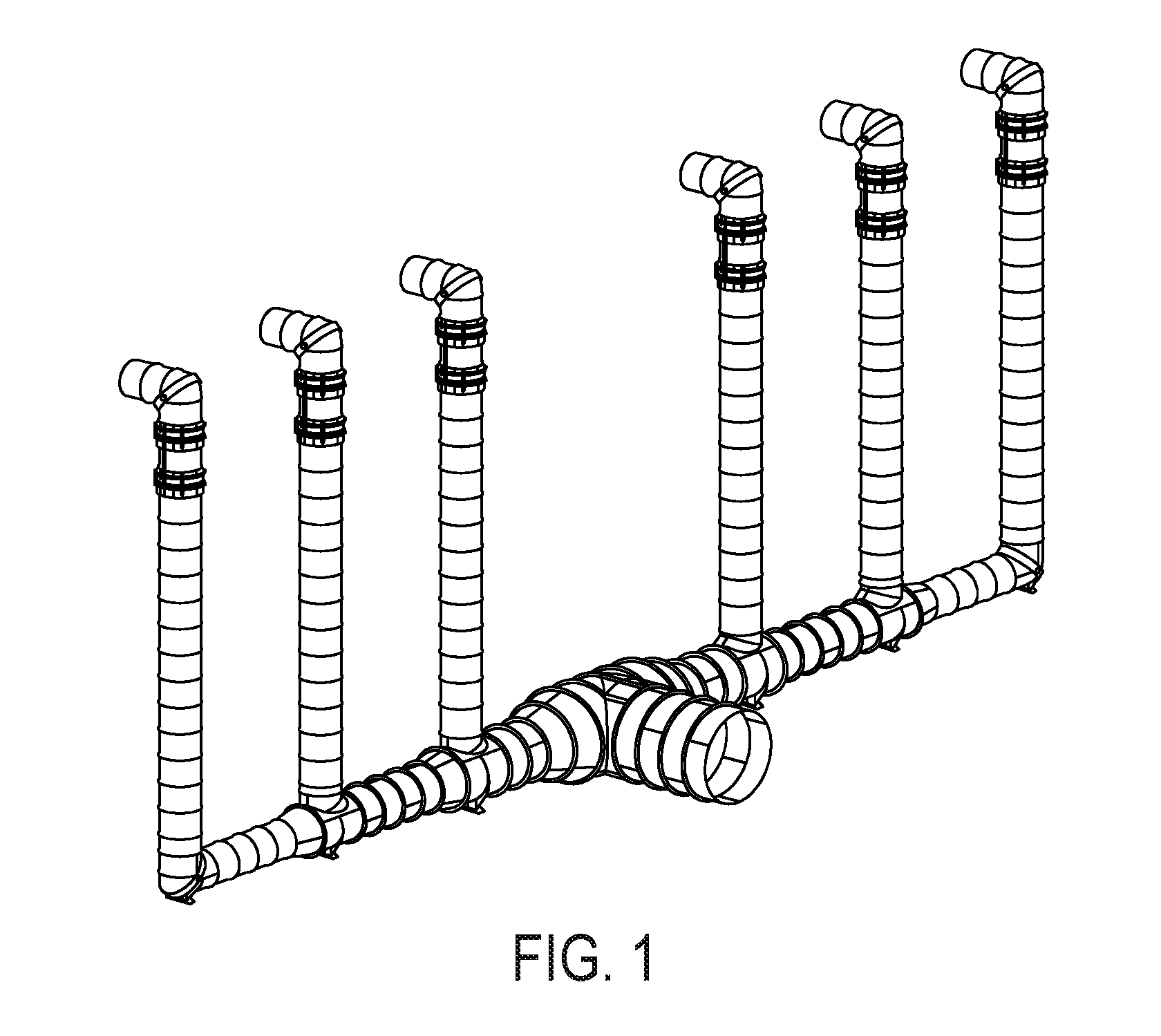
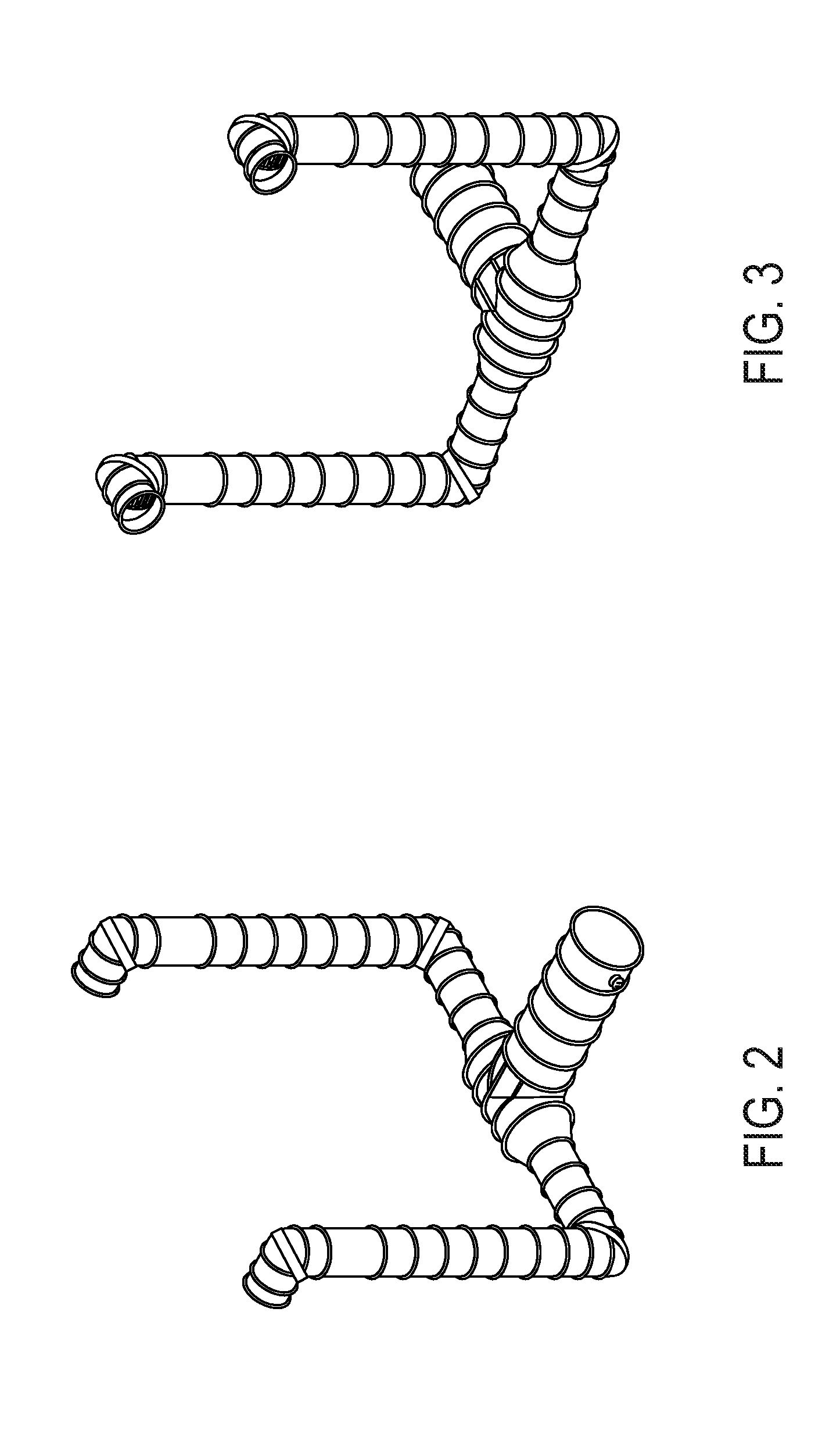
[0037]FIG. 8 shows a double duct turbine exhaust duct system according to an embodiment of the invention. Prior art turbine exhaust systems approach an industrial air cooled condenser with a single duct and then divide the steam exhaust in opposite directions using a large and complicated T-piece fitted with guide vanes, see, e.g., FIGS. 1-3. In contrast, FIG. 8 shows an embodiment of the invention in which the steam exhaust either leaves the turbine or turbine transition piece in two separate streams or is divided into two separate streams shortly after it leaves the turbine transition piece. Each exhaust stream then separately approaches the ACC in its own turbine exhaust duct, and then is turned, without splitting, to fl...


PUM


Abstract

A double turbine exhaust duct design and an inline V turbine exhaust duct design that both eliminate the need for the standard T-piece in a turbine exhaust duct assembly, substantially reducing the steam-side pressure drop, minimizing the sub-cooling in the steam cycle (the temperature difference between ACC condensate temperature out and turbine steam temperature), thus improving the overall efficiency of the steam cycle plant heat rate.

Description

CROSS REFERENCE TO RELATED APPLICATION[0001]This application claims priority from U.S. Provisional Application No. 61 / 653,613 filed on May 31, 2012, and entitled “IMPROVED TURBINE EXHAUST DUCT DESIGN,” the specification of which is incorporated herein by reference in its entirety.FIELD OF THE INVENTION[0002]The present invention relates to air cooled condensers. In particular, the invention relates to new designs for turbine exhaust ducts for air cooled condensers.BACKGROUND OF THE INVENTION[0003]Air cooled condensers are used in the power generation industry to cool the steam exhaust from a steam turbine and convert it to water for return to the power generation cycle. The spent steam from a power generation steam turbine is typically delivered to a turbine exhaust duct which carries the steam to multiple air cooled condenser sections or “streets,” arranged in parallel. According to typical arrangements, a horizontal turbine exhaust duct approaches the center of the air cooled cond...

Claims


Application Information

Patent Timeline
Patent Type & Authority Applications(United States)
IPC IPC(8): F01K7/00
CPCF01D25/32F01D25/30F01K7/00F01D1/24F28B9/02
Inventor DE LAUSNAY, RAF
Owner EVAPCO
Why Eureka
Try Eureka