Apparatus and Method for Connecting Air Cooled Condenser Heat Exchanger Coils to Steam Distribution Manifold
- Summary
- Abstract
- Description
- Claims
- Application Information
AI Technical Summary
Benefits of technology
Problems solved by technology
Method used
Image
Examples
first embodiment
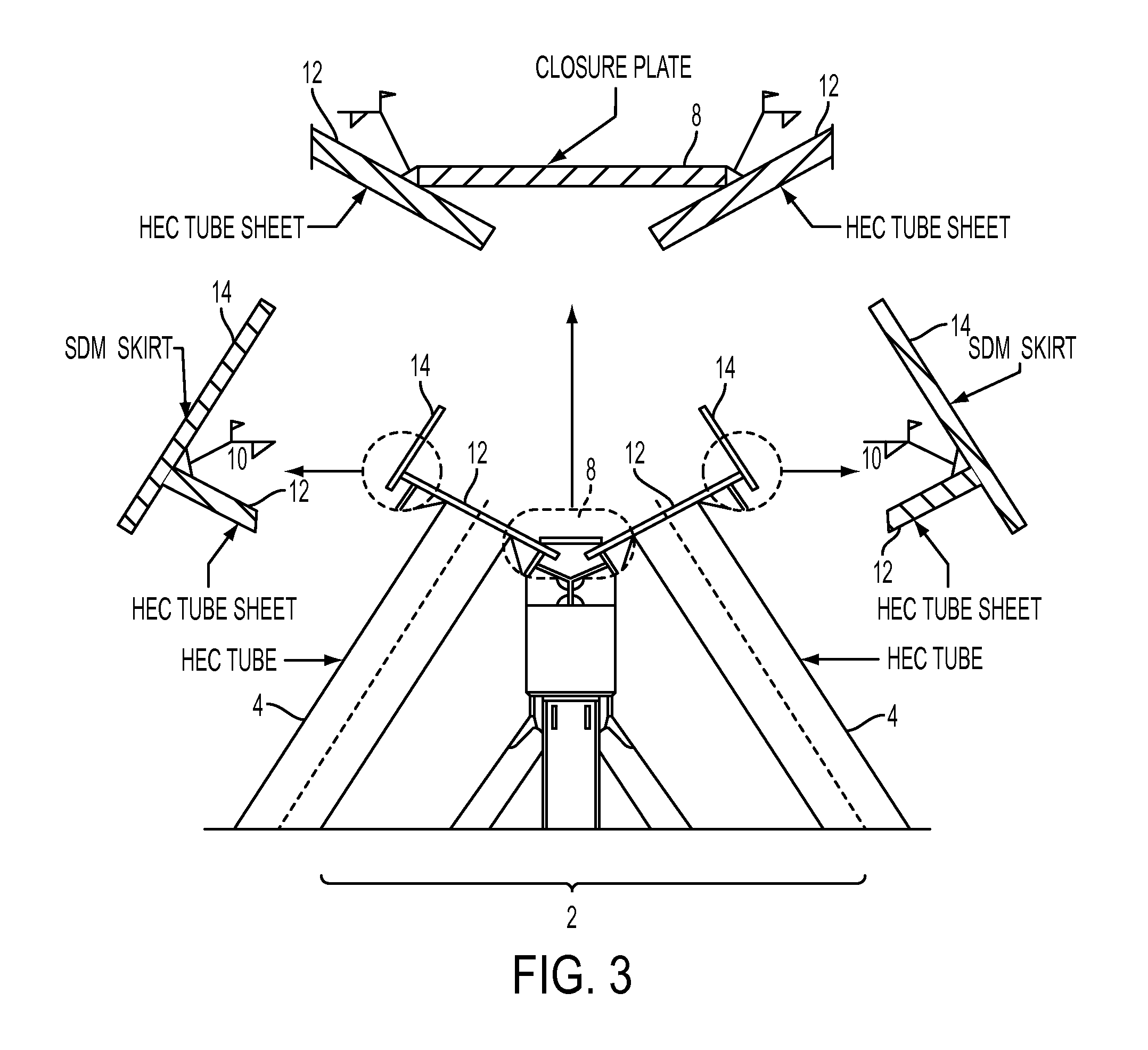
[0045]FIGS. 6A through 6D, 7 and 8 show the invention in which the closure plate 8 is replaced with an angle 16, that is, an L-shaped piece of steel. During the factory manufacture process, angle 16 is shop welded to the tube sheets 12a of one half of the heat exchange coils. According to a preferred embodiment, the end of tube sheets 12a may be angled or beveled to fit flush or nearly flush against a face of the angle 16. The preferred locations of the shop welds are shown in FIGS. 6A and 6B.
[0046]For assembly of an ACC according to this first embodiment of the invention, one half of the primary heat exchanger coils that are shipped to the assembly location include the shop welded angle, and the other one half of the primary heat exchanger coils have a generally standard configuration. During assembly of the heat exchanger A-frame 2 at the assembly location, one modified heat exchanger coil bearing the shop welded angle is positioned opposite a generally standard configuration heat...
second embodiment
[0047]FIGS. 9A through 9C show the invention in which one half of the primary heat exchanger coils are fitted with an extended and bent tube sheet 18, and the other half of the primary heat exchanger coils may have the standard configuration. The length of the extension and angle of the bend is configured to generally allow for a flush connection between the top face of the bend and the edge of the tube sheet of the heat exchanger coil to which it will be welded during site assembly.
[0048]For assembly of an ACC according to this embodiment of the invention, one half of the primary heat exchanger coils that are shipped to the assembly location include the extended and bent tube sheet, and the other one half of the primary heat exchanger coils have a generally standard configuration. During assembly of the heat exchanger A-frame 2 at the assembly location, one modified heat exchanger coil bearing the extended and bent tube sheet 18 is positioned opposite a generally standard configura...
third embodiment
[0049]FIGS. 10A through 10C show the invention in which the closure plate 8 is replaced with an inverted V-shaped length of steel 20 that is shop welded at the factory to the tube sheets 12a of one half of the primary heat exchange coils. According to a preferred embodiment, the end of tube sheets 12a need not be angled or beveled to fit flush or nearly flush against a face of the V-shaped length of steel 20.
[0050]For assembly of an ACC according to this third embodiment of the invention, one half of the primary heat exchanger coils that are shipped to the assembly location include the shop welded inverted V-shaped length of steel 20, and the other one half of the primary heat exchanger coils have a generally standard configuration. During assembly of the heat exchanger A-frame 2 at the assembly location, one modified heat exchanger coil bearing the shop welded V-shaped length of steel 20 is positioned opposite a generally standard configuration heat exchanger coil, and the inner ed...
PUM
| Property | Measurement | Unit |
|---|---|---|
| Length | aaaaa | aaaaa |
Abstract
Description
Claims
Application Information
 - R&D
- Intellectual Property
- Life Sciences
- Materials
- Tech Scout
- Unparalleled Data Quality
- Higher Quality Content
- 60% Fewer Hallucinations
Browse by: Latest US Patents, China's latest patents, Technical Efficacy Thesaurus, Application Domain, Technology Topic, Popular Technical Reports.
© 2025 PatSnap. All rights reserved.Legal|Privacy policy|Modern Slavery Act Transparency Statement|Sitemap|About US| Contact US: help@patsnap.com


