
Water purifying device

a water purification device and water treatment technology, applied in the direction of membranes, filtration separation, separation processes, etc., can solve the problems of limited use, heavy distillation equipment, and water purification devices that are hardly portable outdoors or at sea, and achieve portability and ease of use.

Inactive Publication Date: 2013-12-19
CHEN YING CHI
View PDF5 Cites 0 Cited by
  • Summary
  • Abstract
  • Description
  • Claims
  • Application Information

AI Technical Summary

Benefits of technology

The present invention provides a water purification device that uses the pressure of sewer water as a filtration function. The device is portable and easy to use. It has a container with a body and a lid, and a filtration unit that can be placed at either the lid or the opening of the body. The container is made of plastic material and has a supporting slat to prevent compression and deformation when submerged in sewer water. Additionally, the device can be hung with a heavy object to increase its weight.

Problems solved by technology

Distillation apparatuses are so bulky that their use is restricted to distilled water manufacturers.
The pressurization apparatus adds to the volume of the water purification device; as a result, the water purification device is hardly portable outdoors or at sea.
However, a manually pressurizing pump is not only structurally intricate but also susceptible to damage caused by a loosened screw or a severed lever, thereby lacking ease of use.
Although the conventional water purification device does not consume additional energy, users find its long stainless steel pipe inconvenient to carry.
Another drawback of the conventional water purification device is that the water pressure inside the pipe depends on the length of the pipe.
Hence, a 1.5 m stainless steel pipe generates a maximum water pressure of 0.15 Kg / cm2 approximately, which is insufficient to enable the RO membrane to function efficiently.
If the pipe is lengthened, the pipe will become overly bulky and heavy.
Furthermore, if the water purification device is not equipped with a support, the user will have to grip the pipe by hand in order to submerge the pipe in water for 10 to 30 minutes laboriously, thereby posing a threat to the health or even safety of the user outdoors or at sea.
In consideration of its aforesaid drawbacks, the conventional manually-operated water purification device is neither practical nor convenient to use.

Method used


Image

  • Water purifying device
  • Water purifying device
  • Water purifying device

Examples


Embodiment Construction

[0018]The present invention is hereunder described and illustrated with preferred embodiments and drawings. Words, such as “internal” and “external”, which are indicative of directions, are comprehensible to laymen in terms of their understanding of a water container. Like elements in the embodiments are denoted with like reference numerals to facilitate the identification thereof.

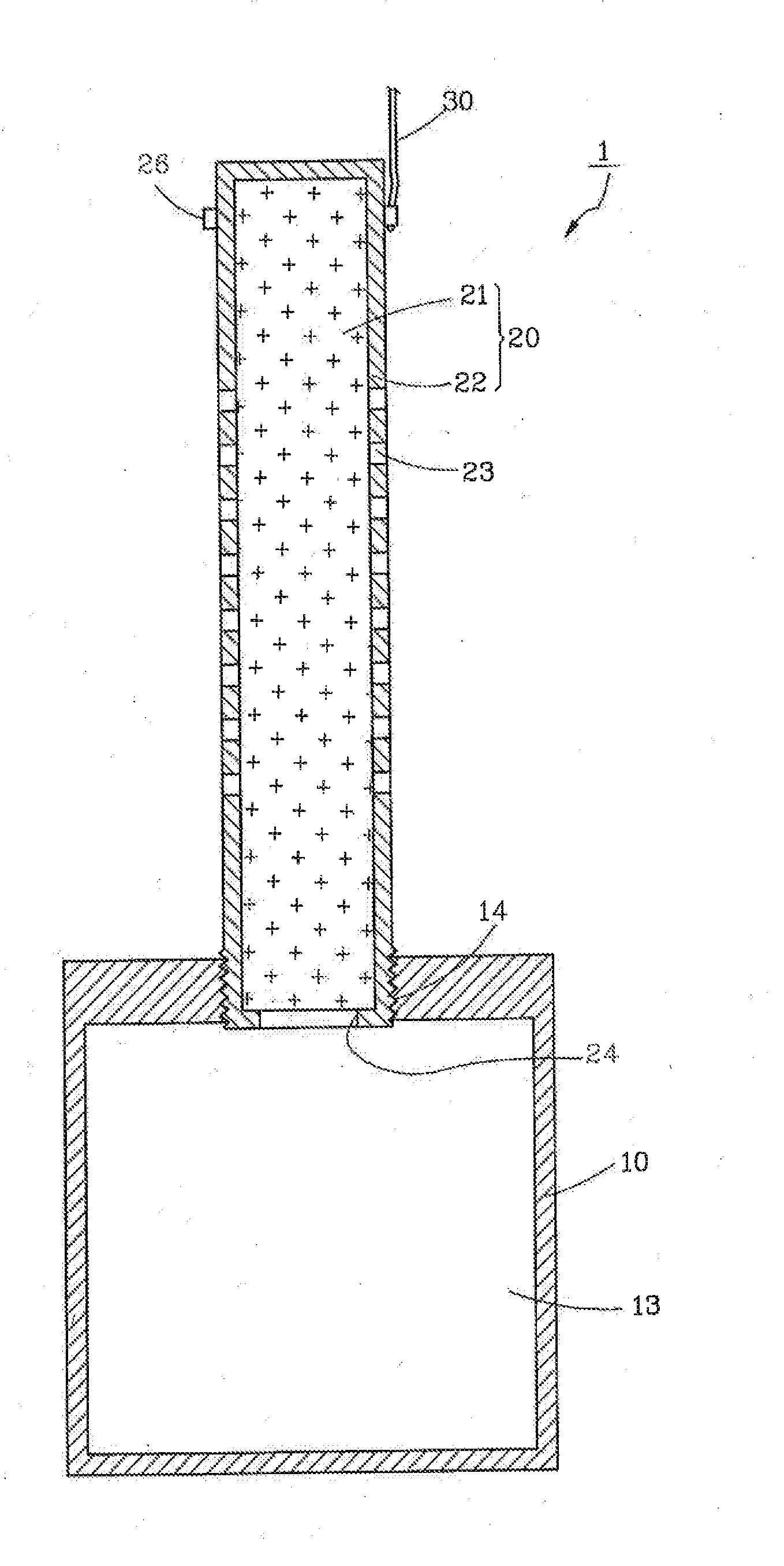
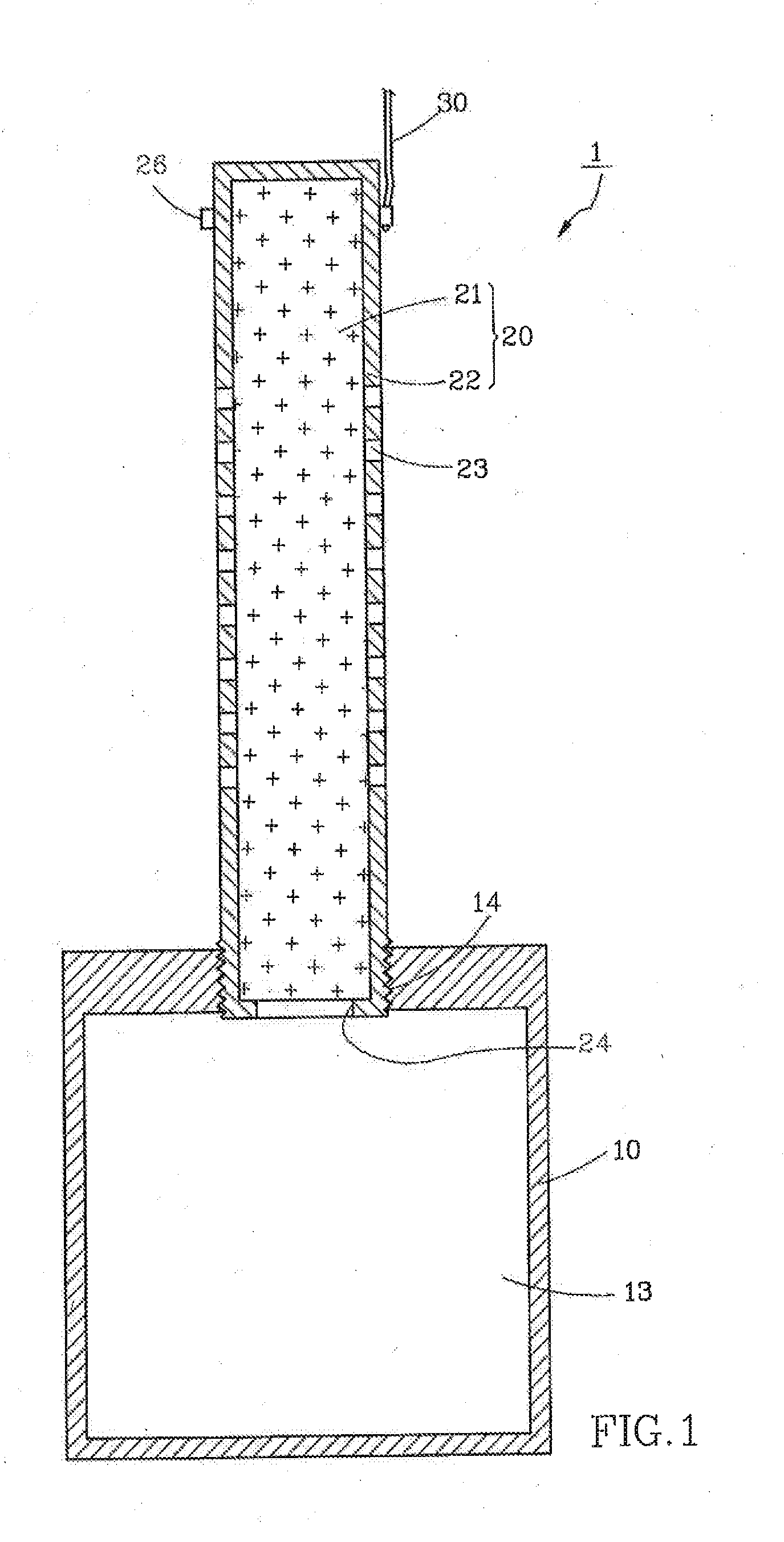
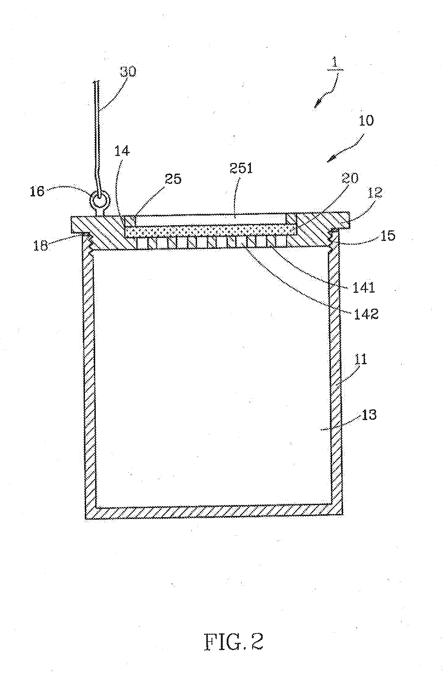
[0019]Referring to FIG. 1, in the first embodiment of the present invention, a water purification device 1 comprises a container 10, a filtration unit 20 disposed on the external surface of the container 10, and a trailing cable 30 connected to one end of the filtration unit 20.

[0020]The container 10 has therein a chamber 13 and a first opening 14 in communication with the chamber 13. The first opening 14 is a screw hole. The container 10 is made of a metal, such as stainless steel, and is a cylindrical container which is 11 cm in diameter, 13.7 cm in height, with the thickness of 0.5 cm, and with an inter...


PUM

PropertyMeasurementUnit
depthaaaaaaaaaa
thicknessaaaaaaaaaa
diameteraaaaaaaaaa

Abstract

A water purification device includes a container, at least a filtration unit, and a trailing cable connected to the container or the filtration unit. The container has therein a chamber and at least a first opening in communication with the chamber. The filtration unit is disposed in the first opening to admit sewer water and thus remove most impurities therefrom. Accordingly, the water purification device sinks spontaneously into the sewer water to be filtered so as, to filter the external sewer water by means of water pressure and thus produce drinking water.

Description

BACKGROUND OF THE INVENTION[0001]1. Technical Field[0002]The present invention relates to water treatment apparatuses defined by IPC, C02F, and more particularly, to a water purification device which is easy to use and portable.[0003]2. Description of Related Art[0004]Water is one of the most valuable resources available on the Earth. Drinking water is required for the survival of human beings. To obtain clean drinking water, conventional water purification processes usually entail filtering impurities and bacteria out of sewer water by distillation and filtration. Distillation apparatuses are so bulky that their use is restricted to distilled water manufacturers. By contrast, households usually resort to filtration-based water purification technology. One of the prerequisites for filtration-based water purification technology is applying a specific operating pressure, whether by hand, by electric power, or by a pressurization apparatus, such as a water tower, so that, under the ope...

Claims


Application Information

Patent Timeline
Patent Type & Authority Applications(United States)
IPC IPC(8): C02F1/00
CPCC02F1/002C02F1/441C02F2201/006B01D61/025B01D61/08B01D63/087B01D69/10B01D2313/00B01D2313/02B01D2313/06B01D2313/24B01D2315/06B01D2313/201B01D2313/041
Inventor CHEN, YING-CHI
Owner CHEN YING CHI
Features
  • Generate Ideas
  • Intellectual Property
  • Life Sciences
  • Materials
  • Tech Scout
  • Unparalleled Data Quality
  • Higher Quality Content
  • 60% Fewer Hallucinations
Learn More