Adaptive estimation of frame time stamp latency

a frame time stamp and estimation technology, applied in the field of image processing, can solve the problems of poor robustness of computer vision based tracking methods, many current mobile devices without time stamp fields, and inaccurate sensor time stamps

Active Publication Date: 2013-12-19
QUALCOMM INC
View PDF3 Cites 47 Cited by
  • Summary
  • Abstract
  • Description
  • Claims
  • Application Information

AI Technical Summary

Problems solved by technology

Computer vision based tracking methods suffer from a lack of robustness when there are quick motions and, in particular, when there are large image displacements caused by the rotation of the camera.
Unfortunately, many current mobile devices do not have a time stamp field in the camera API.
Sometimes, the low pass filtering is aggressive, effectively averaging measurements over more than one sample and thereby rendering the sensor time stamp inaccurate.
Thus, fusion between poses derived from camera frames and inertial sensor measurements is inaccurate.

Method used


Image

  • Adaptive estimation of frame time stamp latency
  • Adaptive estimation of frame time stamp latency
  • Adaptive estimation of frame time stamp latency

Examples


Embodiment Construction

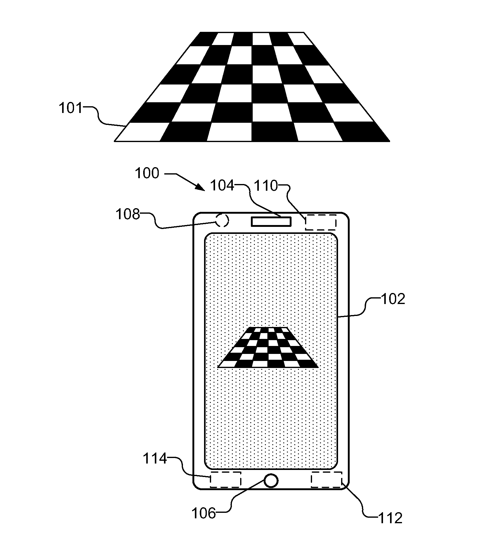
[0017]FIG. 1 illustrates a mobile device 100 capable of compensating for lack of a time stamp when the image frame is captured. The mobile device 100 time stamps the frame after a frame time stamp latency from when the frame has been captured by the camera. For example, a captured frame is not time stamped at the sensor level, e.g., by the camera when captured, but is time stamped later, e.g., when the frame reaches an application level, which may be the High Level Operating System (HLOS), which may be, e.g., Android, iOS, etc, or other level. The frame time stamp latency may be a function of the type of mobile device 100 as well as the camera frame rate, which depends on frame rate which depends on lighting conditions. The mobile device 100 estimates the frame time stamp latency based on a vision based rotation and inertial sensor based rotation, and uses the estimated frame time stamp latency to correct the frame time stamp latency in subsequently captured images.

[0018]As used her...


PUM


Abstract

A mobile device compensates for a lack of a time stamp when an image frame is captured by estimating the frame time stamp latency. The mobile device captures images frames and time stamps each frame after the frame time stamp latency. A vision based rotation is determined from a pair of frames. A plurality of inertia based rotations is measured using time stamped signals from an inertial sensor in the mobile device based on different possible delays between time stamping each frame and time stamps on the signals from the inertial sensors. The determined rotations may be about the camera's optical axis. The vision based rotation is compared to the plurality of inertia based rotations to determine an estimated frame time stamp latency, which is used to correct the frame time stamp latency when time stamping subsequently captured frames. A median latency determined using different frame pairs may be used.

Description

BACKGROUND[0001]1. Background Field[0002]Embodiments of the subject matter described herein are related generally to image processing, and more particularly compensating for the lack of a time stamp when images are captured.[0003]2. Relevant Background[0004]Computer vision based tracking methods suffer from a lack of robustness when there are quick motions and, in particular, when there are large image displacements caused by the rotation of the camera. Hence, aiding computer vision tracking with inertial sensors can drastically improve the tracking robustness. Sensor fusion between poses derived from camera frames and inertial sensor measurements can only occur if accurate time stamps for camera frames and inertial sensor measurements are available.[0005]In current mobile device platforms, the application program interface (API) for inertial sensors includes a time stamp field and the inertial sensor data is time stamped when the sensor is sampled. Unfortunately, many current mobil...

Claims


Application Information

Patent Timeline
Patent Type & Authority Applications(United States)
IPC IPC(8): H04N7/18
CPCH04N17/002H04N23/6811H04N23/6812
Inventor BRUNNER, CHRISTOPHERRAMACHANDRAN, MAHESHRAMANANDAN, ARVINDCHARI, MURALI RAMASWAMY
Owner QUALCOMM INC
Why Eureka
Try Eureka