Continuous time warp and binocular time warp for virtual and augmented reality display systems and methods

a technology applied in the field of virtual reality and augmented reality visualization systems, can solve the problems of modifying the virtual image displayed, undesired user experience, and difficulty in producing vr or ar, and achieve the effect of reducing the latency of motion to photon

Active Publication Date: 2018-03-01
MAGIC LEAP INC
View PDF6 Cites 42 Cited by
  • Summary
  • Abstract
  • Description
  • Claims
  • Application Information

AI Technical Summary

Benefits of technology

[0011]Various embodiments provide continuous and / or binocular time warping methods to account for head movement of the user and to minimize the motion-to-photon latency resulting from the head movement of the user. Continuous time warping allows for transformation of an image from a first perspective (e.g., based on a first position of the user's head) to a second perspective (e.g., based on a second position of the user's head) without having to re-render the image from the second perspective. In some embodiments, the continuous time warp is performed on an external hardware (e.g., a controller external to the display), and, in other embodiments, the continuous time warp is performed on internal hardware (e.g., a controller internal to the display). The continuous time warp is performed before a final image is displayed at the display device (e.g., a sequential display device).

Problems solved by technology

Due to the extreme complexity of the human visual perception and nervous system, it is challenging to produce a VR or AR technology that facilitates a comfortable, natural-feeling, rich presentation of virtual image elements amongst other virtual or real-world imagery elements.
One major problem is directed to modifying the virtual image displayed to the user based on user movement.
If this change is not accounted for, it may result in an undesired user experience.
Since the content is generated based on the first pose and the user now has the second pose, the generated content displayed to the user will appear misplaced with respect to the user because of pose mismatch.
The pose mismatch may lead to an undesired user experience.
While this technique may work for panel displays that display an image frame by flashing / illuminating all pixels (e.g., in 2 ms) when all pixels are rendered, this technique may not work well with scanning displays that display image frames on a pixel-by-pixel basis (e.g., in 16 ms) in a sequential manner.

Method used


Image

  • Continuous time warp and binocular time warp for virtual and augmented reality display systems and methods
  • Continuous time warp and binocular time warp for virtual and augmented reality display systems and methods
  • Continuous time warp and binocular time warp for virtual and augmented reality display systems and methods

Examples


Embodiment Construction

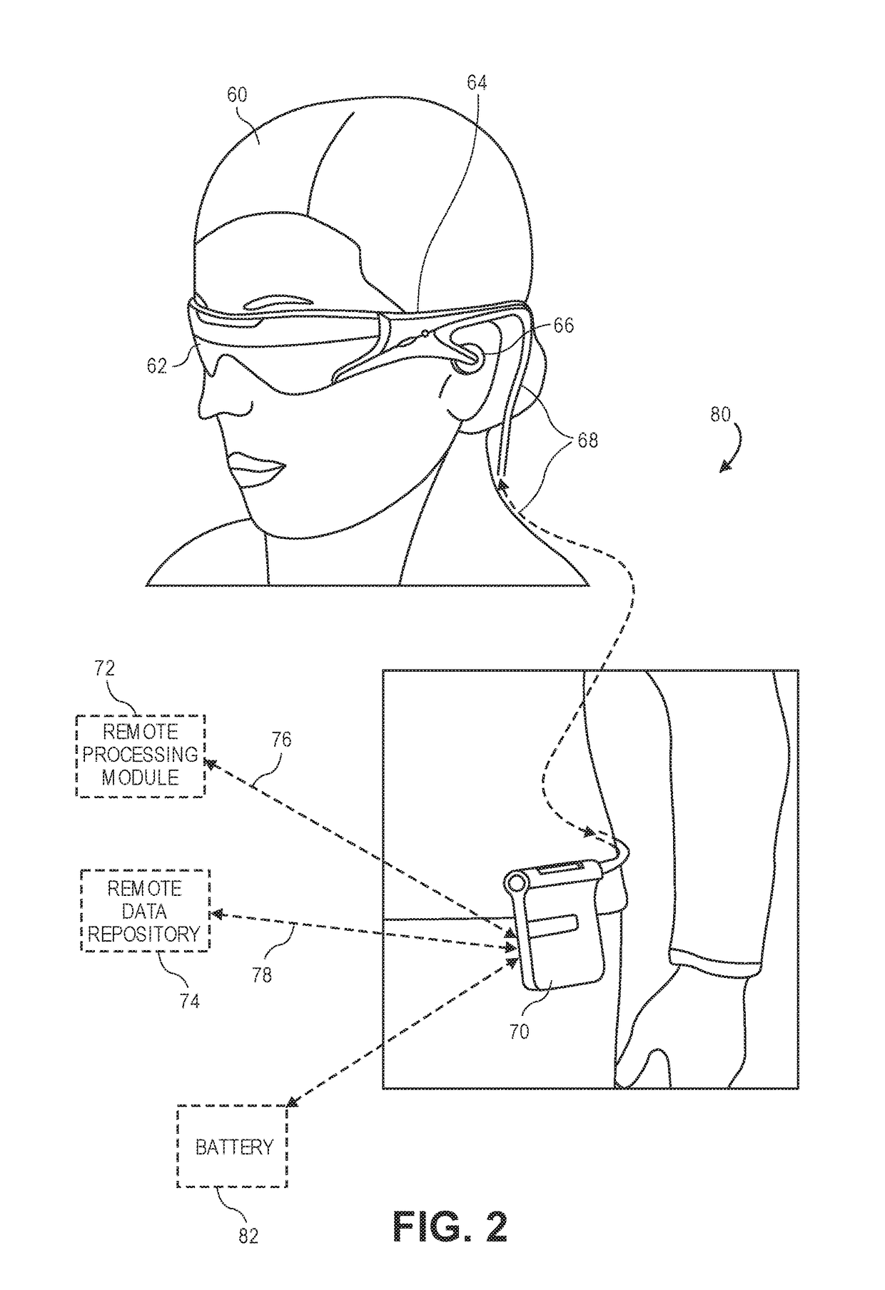
[0046]A virtual reality (“VR”) experience may be provided to a user through a wearable display system. FIG. 2 illustrates an example of wearable display system 80 (hereinafter referred to as “system 80”). The system 80 includes a head mounted display device 62 (hereinafter referred to as “display device 62”), and various mechanical and electronic modules and systems to support the functioning of the display device 62. The display device 62 may be coupled to a frame 64, which is wearable by a display system user or viewer 60 (hereinafter referred to as “user 60”) and configured to position the display device 62 in front of the eyes of the user 60. According to various embodiments, the display device 62 may be a sequential display. The display device 62 may be monocular or binocular. In some embodiments, a speaker 66 is coupled to the frame 64 and positioned proximate an ear canal of the user 60. In some embodiments, another speaker, not shown, is positioned adjacent another ear canal...


PUM


Abstract

Embodiments of the present disclosure relate to continuous and / or binocular time warping methods to account for head movement of the user without having to re-render a displayed image. Continuous time warping allows for transformation of an image from a first perspective to a second perspective of the viewer without having to re-render the image from the second perspective. Binocular time warp refers to the late-frame time warp used in connection with a display device including a left display unit for the left eye and a right display unit for the right eye where the late-frame time warp is performed separately for the left display unit and the right display unit. Warped images are sent to the left and the right display units where photons are generated and emitted toward respective eyes of the viewer, thereby displaying an image on the left and the right display units at the same time.

Description

CROSS-REFERENCES TO RELATED APPLICATIONS[0001]This application is a non-provisional of and claims the benefit of U.S. Patent Application No. 62 / 380,302 titled “Time Warp for Virtual and Augmented Reality Display Systems and Methods”, filed on Aug. 26, 2016, which is herein incorporated by reference in its entirety for all purposes. This application incorporates by reference in their entirety each of the following U.S. Patent Applications: U.S. Provisional Application No. 62 / 313,698 filed on Mar. 25, 2016 (Docket No. MLEAP.058PR1), U.S. patent application Ser. No. 14 / 331,218 filed on Jul. 14, 2014; U.S. patent application Ser. No. 14 / 555,585 filed on Nov. 27, 2014; U.S. patent application Ser. No. 14 / 690,401 filed on Apr. 18, 2015; U.S. patent application Ser. No. 14 / 726,424 filed on May 29, 2015; U.S. patent application Ser. No. 14 / 726,429 filed on May 29, 2015; U.S. patent application Ser. No. 15 / 146,296 filed on May 4, 2016; U.S. patent application Ser. No. 15 / 182,511 filed on Jun...

Claims


Application Information

Patent Timeline
Patent Type & Authority Applications(United States)
IPC IPC(8): G06T15/20G06T19/00G06T15/00G06T1/60
CPCG06T15/205G06T19/006G06F3/012G06T1/60G06T2215/16G06T15/005G06F3/04815G02B2027/014A63F2300/8082H04N13/344H04N13/117H04N13/383G09G5/363G09G5/026G06F3/147G09G2370/20G09G2354/00A63F13/00G02B27/017G06T13/00G06T19/003
Inventor YEOH, IVANEDWIN, LIONELMILLER, SAMUEL A.
Owner MAGIC LEAP INC
Why Eureka
Try Eureka