In-cell multi-touch panel system with low noise and time division multiplexing and its driving method

a multi-touch panel and time division multiplexing technology, applied in the field of touch panels, can solve the problems of difficult to overcome electromagnetic disturbance (emi) and noise, difficult to implement multi-touch, and relatively increasing the weight of the flat display, so as to save costs and reduce nois

Active Publication Date: 2014-12-04
FOCALTECH SYST CO LTD
View PDF14 Cites 41 Cited by
  • Summary
  • Abstract
  • Description
  • Claims
  • Application Information

AI Technical Summary

Benefits of technology

[0021]An object of the present invention is to provide an in-cell multi-touch panel system with low noise and time division multiplexing and its driving method, for allowing the common grounding signal (VCOM) on displaying and the touch driving signal (VIN) on touching to share the same layer of transparent electrical conductor to thereby save the cost, and to use different driving timings for concurrently driving the display and the touch control, so as to solve the prior problem in that the time for the display and touch control is insufficient.
[0022]Another object of the present invention is to provide an in-cell multi-touch panel system with low noise and time division multiplexing and its driving method, which can reduce the affection to a touch detector due to noises generated by the common voltage layer (Vcom), the source voltages of the TFTs on the LCD panel, and the polarity inversion of the panel, and increase the linearity and reliability of coordinate determination of touch points thereby further raising the system SNR.

Problems solved by technology

The surface capacitive touch sensing has a simple configuration, so that the multi-touch implementation is not easy, and the problems of electromagnetic disturbance (EMI) and noises are difficult to be overcome.
However, such a stacking requires an increase of the weight of the touch panel, resulting in relatively increasing the weight of the flat display, which cannot meet with the compact requirement for current markets.
For a further description, when the touch panel and flat display are stacked directly, the increased thickness reduces the transmittance of rays and increases the reflectivity and haziness, resulting in relatively reducing the display quality on the screen.
However, the panel is subjected to noises originated from various sources, such as noises generated by a source voltage of the TFT of the panel and the polarity inversion of the panel, which may seriously interfere the sensing lines of the touch IC and make a touch device to generate an erroneous coordinate determination and an instable problem.
However, the anti-noise capability of a filter is varied with different noise sources, so that the noise interference from the displaying and driving IC to the touch IC may not be effectively overcome.
However, such a time sharing needs a driving IC to drive more and more pixels as a resolution of the panel becomes higher and higher, resulting in requiring longer and longer time.
However, because the display frame rate has to be maintained at 60 Hz and over, i.e., 16.6 ms for each frame, it becomes difficult to perform image displaying and touch sensing in 16.6 ms since the resolution of the panel becomes higher and higher.
Also, the resolution development is further limited, which becomes a serious problem to be solved.
In addition, the electrical field has to continuously alternate the positive and negative polarities for the liquid crystals, so that the noise is relatively high in the panel, resulting in that a touch sensing circuit may make an erroneous determination and generate an instable touch coordinate.

Method used


Image

  • In-cell multi-touch panel system with low noise and time division multiplexing and its driving method
  • In-cell multi-touch panel system with low noise and time division multiplexing and its driving method
  • In-cell multi-touch panel system with low noise and time division multiplexing and its driving method

Examples


Embodiment Construction

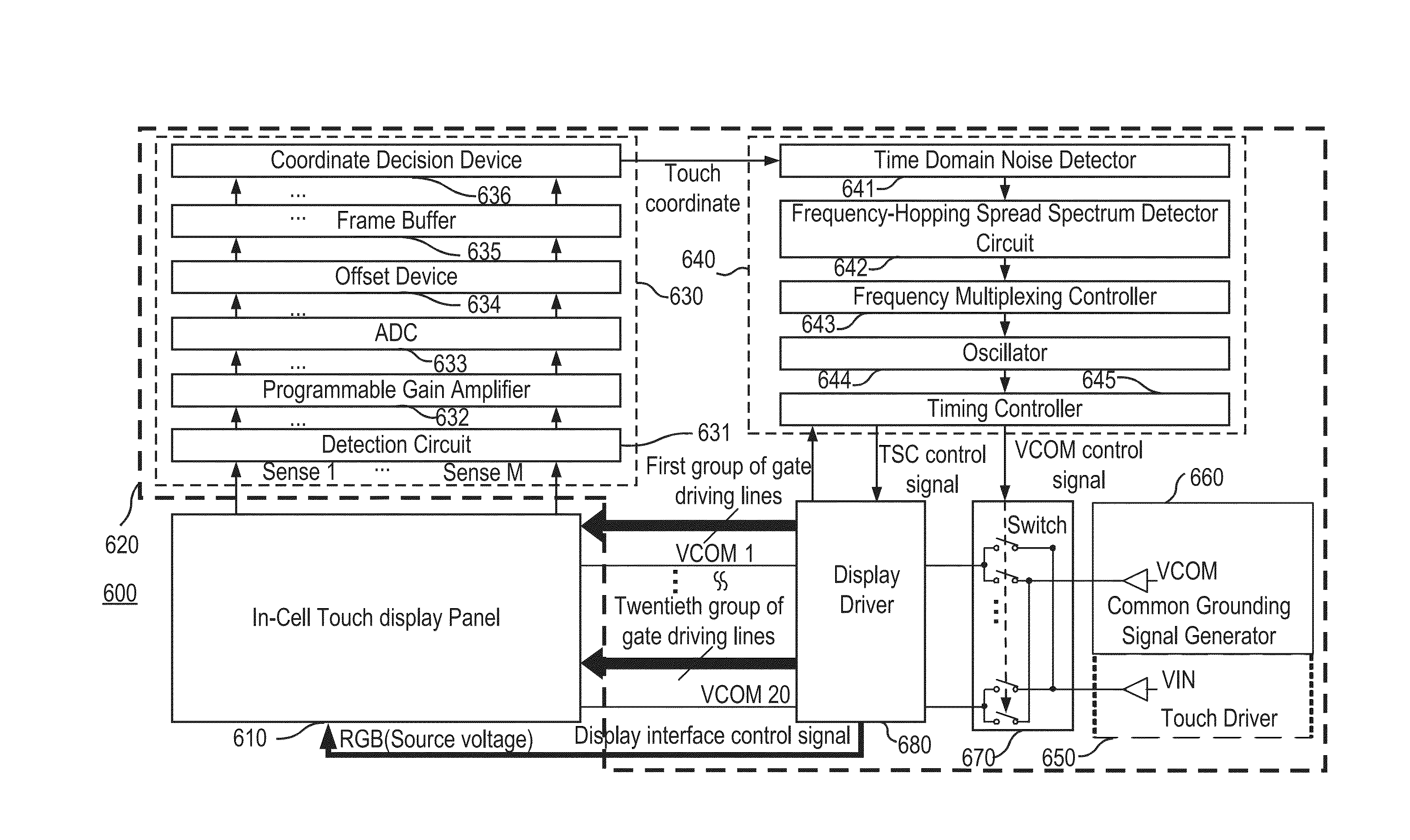
[0039]FIG. 6 is block diagram of an in-cell multi-touch panel system 600 with low noise and time-division multiplexing according to the invention. In FIG. 6, the in-cell multi-touch panel system 600 includes an in-cell touch display panel 610 and a touch display control system 620.

[0040]The in-cell touch display panel 610 displays an image signal and senses an external object.

[0041]The touch display control system 620 is connected to the in-cell touch display panel 610. The touch display control system 620 sequentially outputs a display driving signal to the in-cell touch display panel 610 for displaying the image signal. In addition, the touch display control system 620 sequentially outputs a touch driving signal to the in-cell touch display panel for sampling a sensing voltage from the in-cell touch display panel 610 and determining whether an external object approaches to the in-cell touch display panel. In a first frame time interval, the touch display control system 620 drives ...


PUM


Abstract

An in-cell multi-touch panel system includes: an in-cell touch display panel, a touch display control system. In a first frame time interval, the touch display control system drives the in-cell touch display panel and samples the sensing voltage from the in-cell touch display panel to determine whether there is an approaching external object and noise interference. In a second frame time interval, the touch display control system finds out a frequency with minimum noise for use as a frequency of the touch driving signal when the noise interference exists. In a third frame time interval, the touch display control system is based on the frequency with minimum noise to correspondingly generate the touch driving signal so as to determine whether there is an approaching external object.

Description

BACKGROUND OF THE INVENTION[0001]1. Field of the Invention[0002]The present invention relates to the technical field of touch panels and, more particularly, to an in-cell multi-touch panel system with low noise and time division multiplexing and its driving method.[0003]2. Description of Related Art[0004]The principle of touch panels is based on different sensing manners to detect a voltage, current, acoustic wave, or infrared to thereby detect the coordinates of touch points on a screen where a finger or other medium touches. For example, a resistive touch panel uses a voltage difference between the upper and lower electrodes to compute the position of a pressed point for detecting the location of the touch point, and a capacitive touch panel uses a capacitance change generated in an electrostatic combination of the arranged transparent electrodes and a human body to generate a current or voltage for detecting touching coordinates.[0005]Upon the principle, the capacitive touch tech...

Claims


Application Information

Patent Timeline
Patent Type & Authority Applications(United States)
IPC IPC(8): G06F3/044
CPCG06F3/044G06F3/0443G06F2203/04104
Inventor WANG, HSIN-HAOHUANG, YEN-LIN
Owner FOCALTECH SYST CO LTD
Why Eureka
Try Eureka