
Distributed flow control system and method for GPRS networks based on leaky buckets

a technology of distributed flow control and buckets, which is applied in the field of distributed flow control system and method for general packet radio service (gprs) networks, can solve the problems of inability to achieve allowable peak and average rates, limited memory space of packet control units (pcus), and inability to add additional boxes or hardwar

Inactive Publication Date: 2003-06-10
LENOVO INNOVATIONS LTD HONG KONG
View PDF6 Cites 43 Cited by
  • Summary
  • Abstract
  • Description
  • Claims
  • Application Information

AI Technical Summary

Problems solved by technology

One problem that exists for the data packet coming from the GGSN 20 (or outside) to the SGSN 24 and then to the BSS / PCU 28 is that the packet control unit (PCU) may have limited memory space.
A main problem arises when multiple sources belonging to the same BVC exist at the SGSN side of the GPRS network 10.
However, the problem is not limited to multiple sources that are multiple routers.
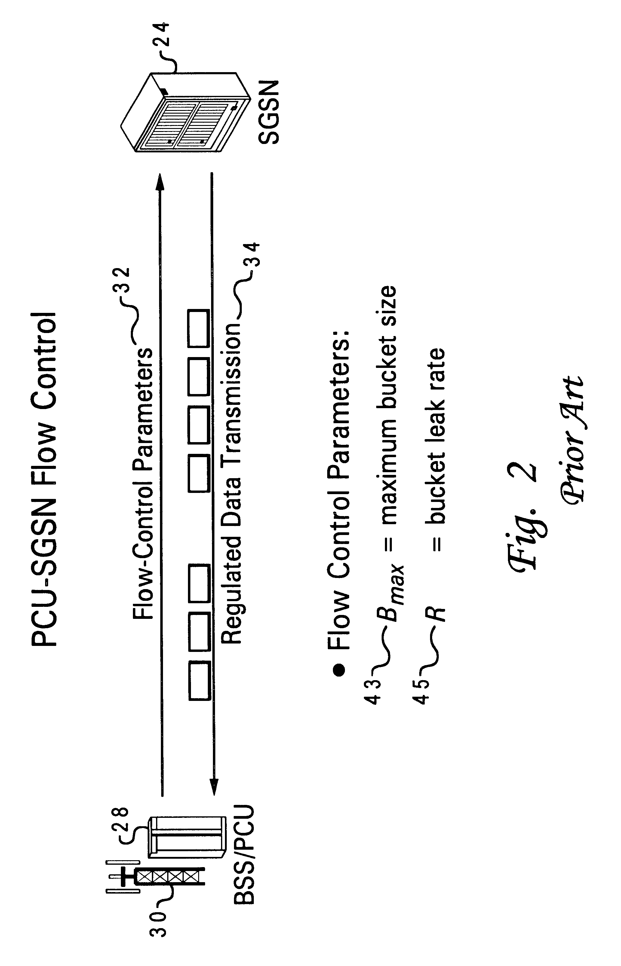
However, since the BSS / PCU 28 is limited to providing only one set of leaky bucket parameters for controlling data flow, the issue becomes how to dimension all of the leaky buckets 36 using only one set of parameters to provide flow control of data.
However, all of these solutions or attempted solutions either fail to enforce the required peak and average rates (i.e. first solution failure) or are overly restrictive such that the allowable peak and average rates cannot be achieved (i.e. second and third solutions failures).
However, the adding of an additional box or hardware is not desired due to space, cost, and other such issues that arise from utilizing additional hardware.
An additional frame of data is prohibited from being sent from the respective source to the single destination when transmission of the data frame will result in the overflow of the leaky bucket.

Method used


Image

  • Distributed flow control system and method for GPRS networks based on leaky buckets
  • Distributed flow control system and method for GPRS networks based on leaky buckets
  • Distributed flow control system and method for GPRS networks based on leaky buckets

Examples


Embodiment Construction

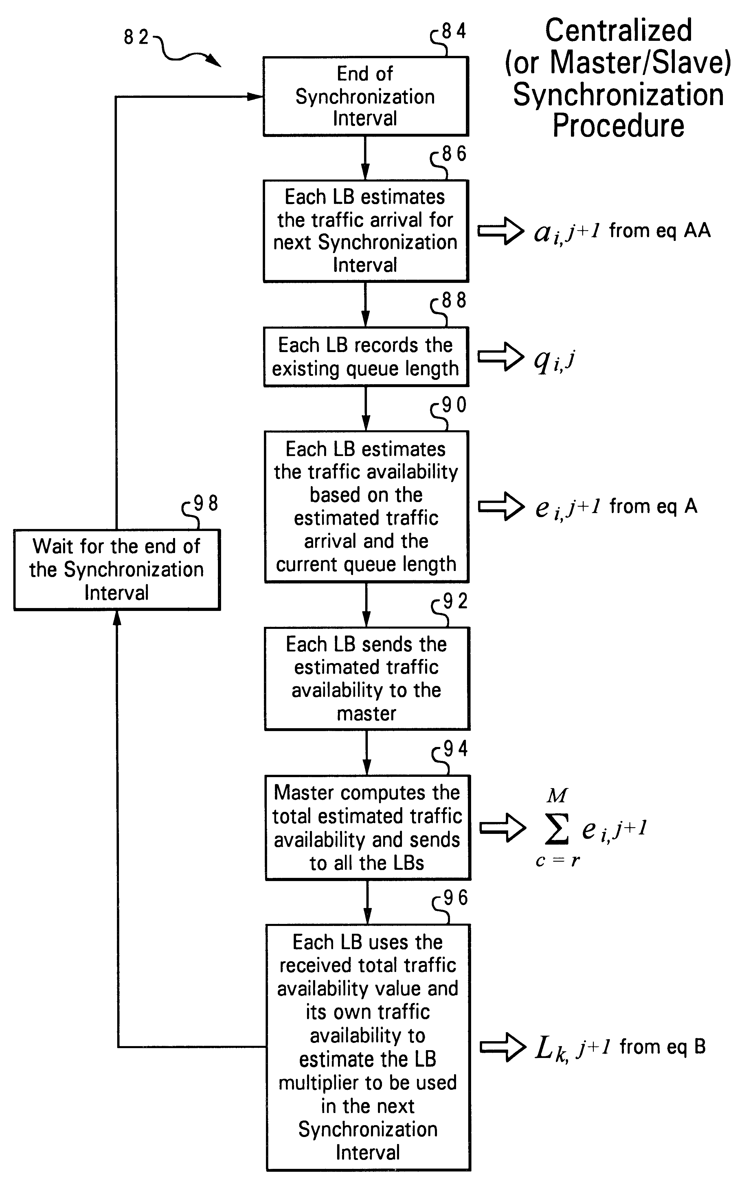
The present invention is a distributed flow control system and method for GPRS networks to control and regulate data flow between multiple sources exist at the SGSN side of the GPRS network and a single destination at the BSS / PCU side of the GPRS network. The present distributed flow control system and method for GPRS networks ensures the departing traffic from all of the sources conforms to the peak and average rate requirements that have been set forth by the BSS / PCU. The present distributed flow control system and method for GPRS networks dimension all of the leaky bucket mechanisms using only one set of leaky bucket parameters to control flow of data. The present distributed flow control system and method for GPRS networks avoids the use of an additional box or hardware for being able to implement the leaky bucket flow control mechanism when multiple sources exist at the SGSN side of the GPRS network.

The present distributed flow control mechanism 52 ensures that the combined dep...


PUM


Abstract

A distributed flow control system and method for GPRS networks to control and regulate data flow between multiple sources and a single destination within a GPRS network. The present system and method ensures the departing traffic from all of the sources conforms to the peak and average rate requirements that have been set forth by the BSS / PCU. A leaky bucket flow control mechanism is used at each respective one of the multiple sources for controlling flow of data from each respective source to the single destination. A maximum bucket size of a leaky bucket and a bucket leak rate are defined for each leaky bucket flow control mechanism. A multiplier (L) is estimated and determined for each respective source based on recent data arrival behaviors of the multiple sources. When a frame of the data is sent from the respective source to the single destination, a number of bytes equal to the size of the transmitted frame times the multiplier L is added to the leaky bucket.

Description

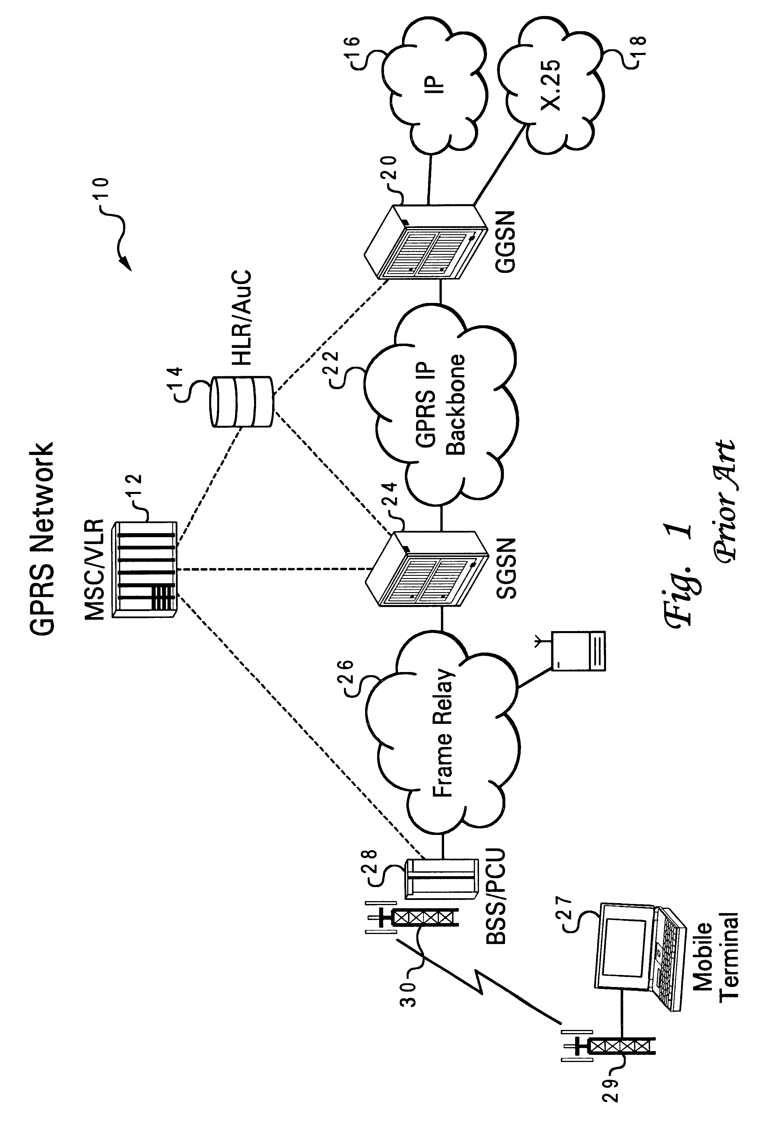
1. Technical FieldThe present invention relates in general to a distributed flow control system and method for General Packet Radio Service (GPRS) networks and in particular to a system and method for adapting a leaky bucket mechanism to a system having multiple traffic sources wherein the combined traffic from all sources must satisfy a single set of peak and average rate requirements.2. Description of the Related ArtWireless communication technologies require the use of various defined standards such as for voice and data communications. General Packet Radio Service (GPRS) is a relatively newer version standard that has been established for wireless data communications in Europe, and GPRS is able to be used anywhere in the world. A general prior art diagram of the topology of a GPRS network 10 is shown in FIG. 1. The GPRS network 10 generally comprises a number of nodes. The GPRS network 10 comprises a mobile switching center (MSC), a visitor location register (VLR) 12, a home loc...

Claims


Application Information

Patent Timeline
IPC IPC(8): H04Q7/22H04L12/56H04W28/14H04W84/04
CPCH04L47/10H04L47/14H04L47/21H04L47/30H04W28/14H04L47/266H04W84/04H04L2012/5637H04W8/04
Inventor HO, JOSEPH S.ZHU, YIXINHANSON, MARK ERIC
Owner LENOVO INNOVATIONS LTD HONG KONG
Learn More