Drive method for pixel circuit

A pixel circuit and driving method technology, which is applied in the field of pixel circuit driving, can solve the problem that the brightness cannot reach the target brightness value in the initial period, and achieve the effect of improving the display effect and improving the hysteresis effect

Active Publication Date: 2018-02-09
SHANGHAI TIANMA MICRO ELECTRONICS CO LTD
View PDF5 Cites 43 Cited by
  • Summary
  • Abstract
  • Description
  • Claims
  • Application Information

AI Technical Summary

Problems solved by technology

[0004] The invention provides a driving method of a pixel circuit to improve the hysteresis effect of the driving transistor, solve the problem that the brightne...

Method used


Image

  • Drive method for pixel circuit
  • Drive method for pixel circuit
  • Drive method for pixel circuit

Examples


Embodiment Construction

[0026] The present invention will be further described in detail below in conjunction with the accompanying drawings and embodiments. It should be understood that the specific embodiments described here are only used to explain the present invention, but not to limit the present invention. In addition, it should be noted that, for the convenience of description, only some structures related to the present invention are shown in the drawings but not all structures.

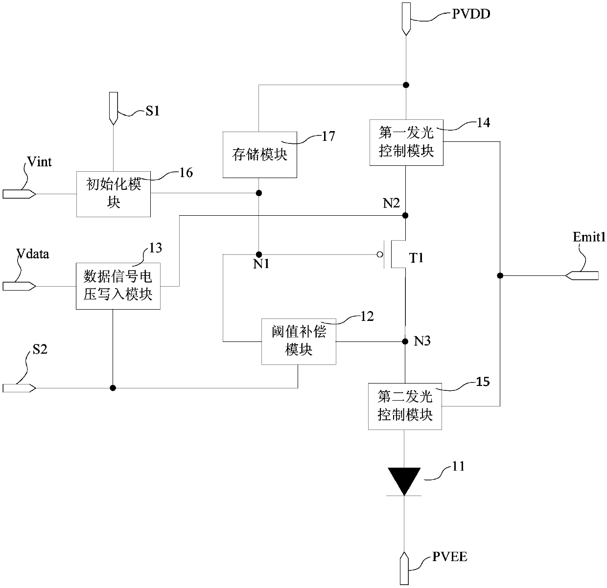
[0027] An embodiment of the present invention provides a driving method for a pixel circuit, wherein the pixel circuit includes a light emitting element, a driving transistor, an initialization module, a data signal voltage writing module, and a storage module;

[0028] The driving method of the reference pixel circuit includes:

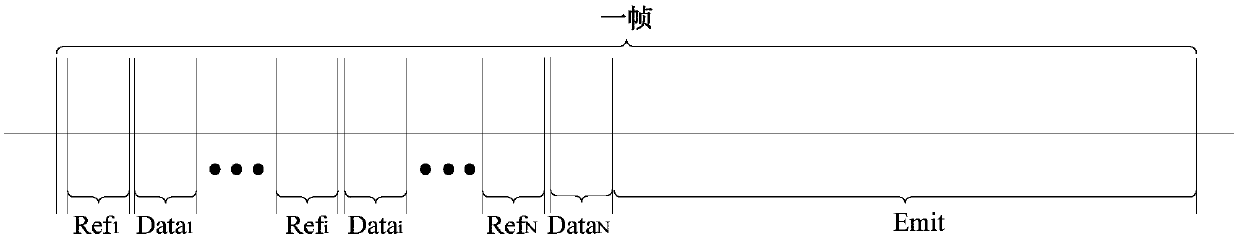
[0029] Within one frame of the display, there are N initialization phases and N data signal voltage writing phases before the light-emitting phase; wherein, the i-th data signal voltage ...


PUM


Abstract

The invention discloses a drive method for a pixel circuit, and the drive method comprises N initialization stages and N data signal voltage writing-in stages in a displayed one-frame time period before a light emitting stage, wherein the i-th data signal voltage writing-in stage is after the i-th initialization stage, and before the (i+1)-th initialization stage, the N-th data signal voltage writing-in stage is after the N-th initialization stage, 1<=i<=N-1, and N is an integer which is greater than 1. At the initialization stage, an initialization module enables an initialization voltage tobe written into a gate electrode of a driving transistor. At the data signal voltage writing-in stage, a data signal voltage writing-in module enables a data signal voltage to be written into the gateelectrode of the driving transistor. A storage module is used for maintaining the gate voltage of the driving transistor. At the light emitting stage, the driving transistor generates a driving current to drive a light emitting element to emit light. According to the technical scheme provided by the embodiment of the invention improves the hysteresis effect of the transistor, and improves the display effect.

Description

technical field [0001] Embodiments of the present invention relate to the field of display technology, and in particular, to a driving method for a pixel circuit. Background technique [0002] Compared with liquid crystal displays, organic light-emitting displays have the advantages of low production cost, low energy consumption, self-illumination, wide viewing angle, and fast response speed. They are currently widely used in display fields such as mobile phones, PDAs, and digital cameras. A plurality of pixel circuits are arranged in the organic light emitting display panel. [0003] A pixel circuit generally includes a driving transistor, several switching transistors and storage capacitors, and the driving current generated by the driving transistor drives the organic light-emitting element to emit light for display. When the pixel displays many frames of black images, the drive transistor is in the cut-off state for a long time. At this time, because the gate potential ...

Claims


Application Information

Patent Timeline
IPC IPC(8): G09G3/3291G09G3/3266
CPCG09G3/3266G09G3/3291G09G2320/0233G09G3/3233G09G2300/0819G09G2300/0842G09G2300/0861G09G2310/0262G09G2320/0257G09G2320/045G09G2310/08G09G3/325
Inventor 周星耀李元
Owner SHANGHAI TIANMA MICRO ELECTRONICS CO LTD
Why Eureka
Try Eureka