Method and assembly for detecting the motion of an element

a technology of motion detection and element, applied in the direction of instruments, galvano-magnetic hall-effect devices, code conversion, etc., can solve the problems of major reduction in signal amplitude, change of directions, signal loss, etc., to improve the immunity of the sensor apparatus, increase the hysteresis, and improve the resistance to major signal fluctuations

Inactive Publication Date: 2006-08-22
ROBERT BOSCH GMBH
View PDF5 Cites 7 Cited by
  • Summary
  • Abstract
  • Description
  • Claims
  • Application Information

AI Technical Summary

Benefits of technology

[0011]Detecting the direction of rotation is advantageously utilized according to the invention to make it possible simply and quickly to distinguish unambiguously between vibration and a genuine rotary motion. Unlike a rotary motion with measurement pulses in an unambiguous direction of rotation (such as left, left, left, et seq.), a rotary oscillation of a transducer wheel of the sensor apparatus is characterized by an alternating direction of rotation (such as right, left, right, left, et seq.).
[0013]The above-described way of evaluating the preferable direction-of-rotation signal makes it possible in a simple way to detect vibration of a transducer wheel in the form of angular vibration and thus to improve the immunity of the sensor apparatus, without the necessity of increasing the hysteresis and thus worsening the resistance to major signal fluctuations.

Problems solved by technology

However, it must be noted that a highly sensitive sensor is intrinsically also highly sensitive to excitation by the vibration that impairs the outcome of measurement and that briefly also causes changes in the directions of rotation.
A substantial disadvantage of this method is the loss of immunity to air gap impacts during operation, which can briefly cause a major reduction in the signal amplitude.
A previously increased hysteresis at the switching point of the sensor, signal loss can then occur in the event of an air gap impact.
However, the behavior of sensors that regardless of the signal frequency furnish a constant internal signal amplitude cannot be improved.

Method used


Image

  • Method and assembly for detecting the motion of an element
  • Method and assembly for detecting the motion of an element

Examples


Embodiment Construction

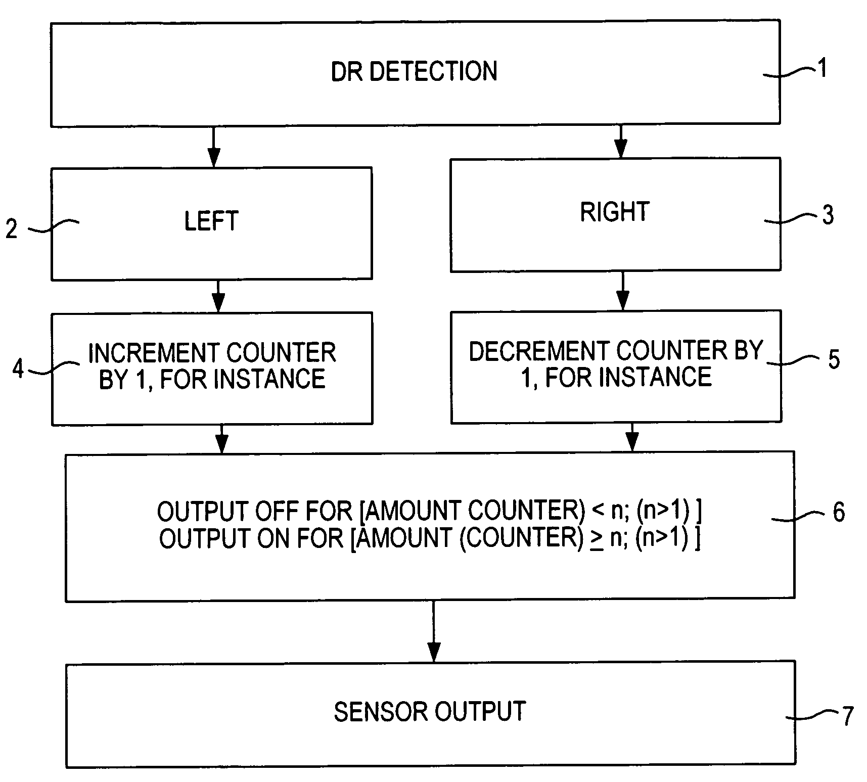
[0018]In FIG. 1, a flow chart is shown for a method for detecting the rotary motion of a transducer wheel, which in principle is known from the prior art, for instance for generating pulses for predetermined angles of rotation, relative to a sensor apparatus. In block 1, a direction of rotation detection circuit is represented symbolically; in block 2, this circuit generates a signal for the rotary motion “left”, and in block 3 it generates a signal for the rotary motion “right”.

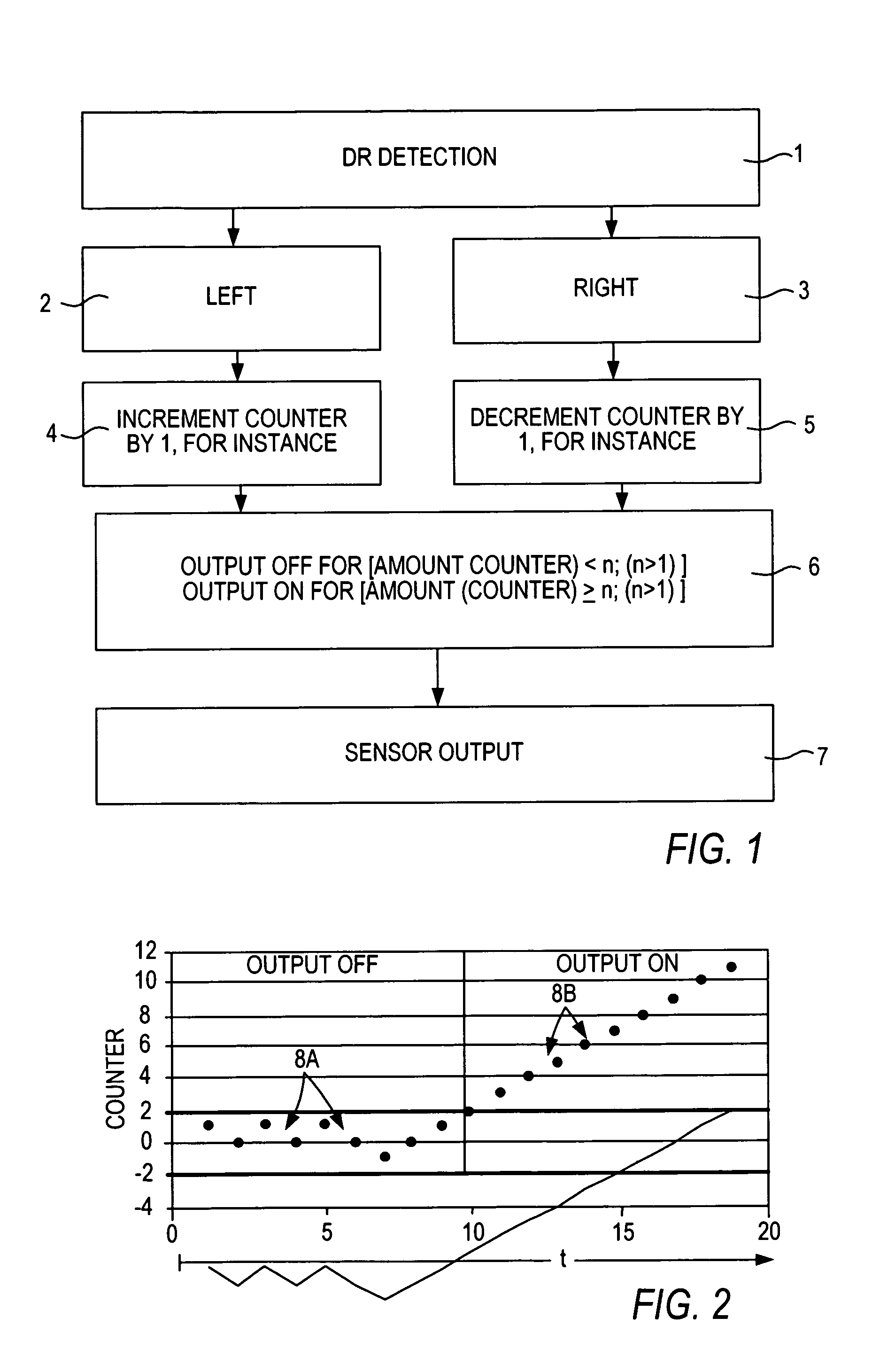
[0019]In the exemplary embodiment of the invention described here, a binary counter state is increased by “1” in block 4 upon the detection of a leftward rotation, and decreased by “1” in block 5 upon detection of a rightward rotation. In a counting logic component 6, the respective counter state is ascertained and evaluated for a sensor output 7, as will be explained in conjunction with a graph shown in FIG. 2.

[0020]FIG. 2 shows the course of the counter state in the counting logic component 6 over a measur...


PUM


Abstract

A method for detecting the motion of an element relative to a sensor apparatus is proposed, in which a detection of the direction of motion is performed. As a function of the direction of motion, a measurement signal is increased or decreased at predetermined measurement intervals, and only if a predetermined threshold value is exceeded is a direction-of-motion signal generated. Preferably, by means of a counting logic circuit (6), a counter is increased by a binary amount In one direction (2) and the counter (6) is decreased by a binary amount in the respective other direction (3). Upon a detection of measurement signals which as a result of being increased or decreased in a measurement interval do not lead to exceeding of the predetermined amount of the threshold value, vibration of the element is assumed.

Description

BACKGROUND OF THE INVENTION[0001]The invention relates to a method and an apparatus for detecting the motion of an element relative to a sensor apparatus, in particular for detecting the angle of rotation of a rotating element by way of a sensor.[0002]Various embodiments of such sensor apparatuses are already in use, for instance in vehicles. For instance with so-called Hall elements as rpm sensors on the wheels for an anti-lock brake system (ABS), as rpm and phase transducers for engine control, or as steering angle sensors for so-called vehicle dynamics control, and for electrical steering aids.[0003]Among the most essential demands made of these rpm sensors, both in ABS and in the field of engines and transmissions, are as large an air gap as feasible and high immunity to vibration. However, it must be noted that a highly sensitive sensor is intrinsically also highly sensitive to excitation by the vibration that impairs the outcome of measurement and that briefly also causes chan...

Claims


Application Information

Patent Timeline
Patent Type & Authority Patents(United States)
IPC IPC(8): G01B7/30G01R33/02G01R33/07G01P3/481G01D5/244G01P13/04H03M1/06H03M1/30
CPCG01D5/24461H03M1/06G01P13/045H03M1/305
Inventor WALTER, KLAUSRETTIG, RASMUSANDRIOT, CHRISTELLEBLOCK, RUEDIGER
Owner ROBERT BOSCH GMBH
Why Eureka
Try Eureka