Concrete member and steel support H-shaped embedded connection joint

A technology for connecting nodes and concrete, which is applied in the direction of building structure and construction, can solve the problems of small node bearing capacity, easy cracking of concrete, and low bearing capacity of connecting nodes, so as to improve the seismic performance and hysteretic performance, and solve the problem of concrete being easy to crack. Cracking, the effect of improving the use efficiency

Active Publication Date: 2013-03-13
SHANGHAI LANKE STEEL STRUCTURE TECH DEV
View PDF9 Cites 6 Cited by
  • Summary
  • Abstract
  • Description
  • Claims
  • Application Information

AI Technical Summary

Problems solved by technology

Although less heavy than steel, the cross-sectional size of the structure is larger, so its self-weight far exceeds the weight of a steel structure of the same span or height
[0007] (2) poor crack resistance
The tensile strength of concrete is very low, therefore, ordinary reinforced concrete structures often work with cracks
Although the existence of cracks does not necessarily mean that the structure is damaged, it affects the durability and aesthetics of the structure
When the number of cracks is large and wide, it will also create a sense of insecurity.
[0008] (3) The energy dissipation performance is not as superior as steel structure
[0011] However, the existing steel support and concrete connection joints need to embed section steel in the concrete member, and the construction is difficult. The arrangement of steel bars in the concrete conflicts w

Method used


Image

  • Concrete member and steel support H-shaped embedded connection joint
  • Concrete member and steel support H-shaped embedded connection joint
  • Concrete member and steel support H-shaped embedded connection joint

Examples


Embodiment Construction

[0041] The technical content of the present invention is further described below in conjunction with accompanying drawing and embodiment:

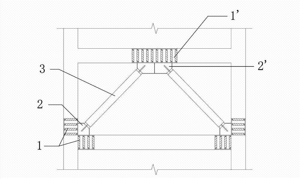
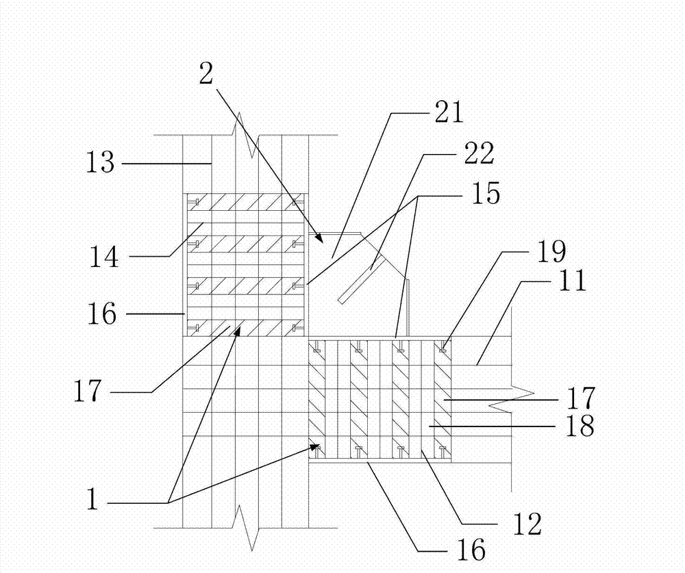
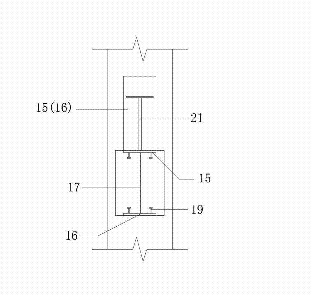
[0042] figure 1According to the first embodiment of the present invention, a schematic diagram of the connection structure between the concrete member and the steel support H-shaped embedded connection node is shown. The concrete member and the steel support H-type pre-embedded connection node are set in the area surrounded by two beams (upper beam and lower beam) and two columns, which mainly include concrete member parts 1 and 1', connection node parts 2 and 2' and steel support 3. Specifically, in figure 1 In the preferred example shown, the concrete member part 1 is arranged at the connection node of the lower beam and the column, and is located in the beam as well as in the column. The concrete member part 1' is arranged at the span of the upper beam and is located inside the beam. The connection node part 2 is connected with the ...


PUM

PropertyMeasurementUnit
Lengthaaaaaaaaaa
Thicknessaaaaaaaaaa
Widthaaaaaaaaaa

Abstract

The invention provides a concrete member and steel support H-shaped embedded connection joint. The concrete member and steel support H-shaped embedded connection joint is arranged between beams and columns of a house. The concrete member and steel support H-shaped embedded connection joint comprises concrete member parts and connection joint parts, wherein each concrete member part comprises concrete beam inner longitudinal bars, concrete beam inner stirrups, concrete column inner longitudinal bars, concrete column inner stirrups, a first steel plate and a second steel plate; each connection joint part comprises a first support connection joint plate, a second support connection joint plate and steel supports; and both ends of each support steel are respectively and mutually connected with the connection joint parts. The concrete member and steel support H-shaped embedded connection joint is characterized in that the corresponding concrete member part also comprises third steel plates. The third steel plates are located between the first steel plate and the second steel plate; one ends of the third steel plates are connected with the first steel plate; and the other ends of the third steel plates are connected with the second steel plate.

Description

technical field [0001] The invention relates to the field of construction engineering, in particular to an H-shaped pre-embedded connection node between a concrete member and a steel support applied between a beam and a column of a house to strengthen the supporting force of the house structure. Background technique [0002] Reinforced concrete frame structures are widely used and have a history of hundreds of years, and have the following advantages: [0003] (1) Take local materials. In reinforced concrete structures, sand and stones account for a large proportion, while cement and steel bars account for a small proportion. Sand and stones can generally be provided near the construction site. [0004] (2) Durable and fire-resistant. The steel bars are buried in the concrete, and the concrete protection is not easy to rust, thus improving the durability of the structure. When a fire occurs, the reinforced concrete structure will not be burned like a wooden structure, nor...

Claims


Application Information

Patent Timeline
IPC IPC(8): E04B1/58E04B1/41
Inventor 宫海刘卓王彦博
Owner SHANGHAI LANKE STEEL STRUCTURE TECH DEV
Why Eureka
Try Eureka