Core block, and magnetic pole core using core blocks for motor

a technology of core blocks and core blocks, applied in the direction of magnetic circuit rotating parts, dynamo-electric machines, magnetic circuit shapes/forms/construction, etc., can solve the problems of difficulty in winding, difficulty in increasing the space factor of winding, and hindering the improvement of motor performance, so as to achieve simple connection structure of adjacent core blocks and high space factor

Inactive Publication Date: 2010-09-16
MABUCHI MOTOR
View PDF5 Cites 22 Cited by
  • Summary
  • Abstract
  • Description
  • Claims
  • Application Information

AI Technical Summary

Benefits of technology

[0012]An object of the present invention is to solve a characteristic problem of a split core; i.e., the requirement of fixation of core blocks of the split core, for employing a split core configuration, which facilitates winding and improves the utilization of material as compared with a unitary core. Another object of the present invention is to restrict a bidirectional movement of the assembled core blocks with respect to a circumferential direction, a radial direction, and a motor's axial direction merely through simple engagement of adjacent core blocks and to enable the insertion, into a motor housing, of the assembled core blocks without need to fixedly join adjacent core blocks by, for example, welding or bonding.
[0017]The present invention employs a split core configuration, which enables the winding of a thick wire and winding with high space factor and enables the manufacture of a high-performance motor. Additionally, according to the present invention, assembled core blocks can be fixed bidirectionally with respect to the circumferential direction, the radial direction, and the motor's axial direction merely through simple engagement of adjacent core blocks. The assembled core blocks can be inserted into a motor housing without need to fixedly join adjacent core blocks by, for example, welding or bonding. Also, according to the present invention, a connection structure for adjacent core blocks is simple. Thus, the present invention can be applied to a small-sized motor.

Problems solved by technology

Such a configuration encounters difficulty in winding by use of a winding machine.
Also, since a space for allowing the passage of the winding nozzle must be provided within a spatial range for winding, difficulty is encountered in increasing the space factor of winding.
Inevitably, improvement in motor performance is hindered.
However, in the case of a small-sized motor, forming an articulated structure is difficult or impossible.
However, in a process of assembling the core blocks into an annular shape subsequent to a winding process and in a process of inserting the core blocks assembled in an annular shape into a housing, no means is available for maintaining the connected core blocks in an annular shape.
Even when jigs are available for such processes, a large number of man-hours are involved.
However, in a state in which such core blocks are assembled without use of, for example, adhesive, the movement of the individual core blocks is restricted, at each connection portion, only in the circumferential direction and unidirectionally with respect to the radial direction.
That is, such a split core involves a problem in that the core blocks assembled without use of adhesive or any other joining means are easily separated from one another.
A similar problem is also involved in a stator core of an outer-rotor-type brushless motor (refer to, for example, Japanese Patent No. 3261074 and Japanese Patent Application Laid-Open (kokai) No.
Stamping out an annular piece having the shape of a magnetic pole core leaves a useless central piece having a large area.

Method used


Image

  • Core block, and magnetic pole core using core blocks for motor
  • Core block, and magnetic pole core using core blocks for motor
  • Core block, and magnetic pole core using core blocks for motor

Examples


first embodiment

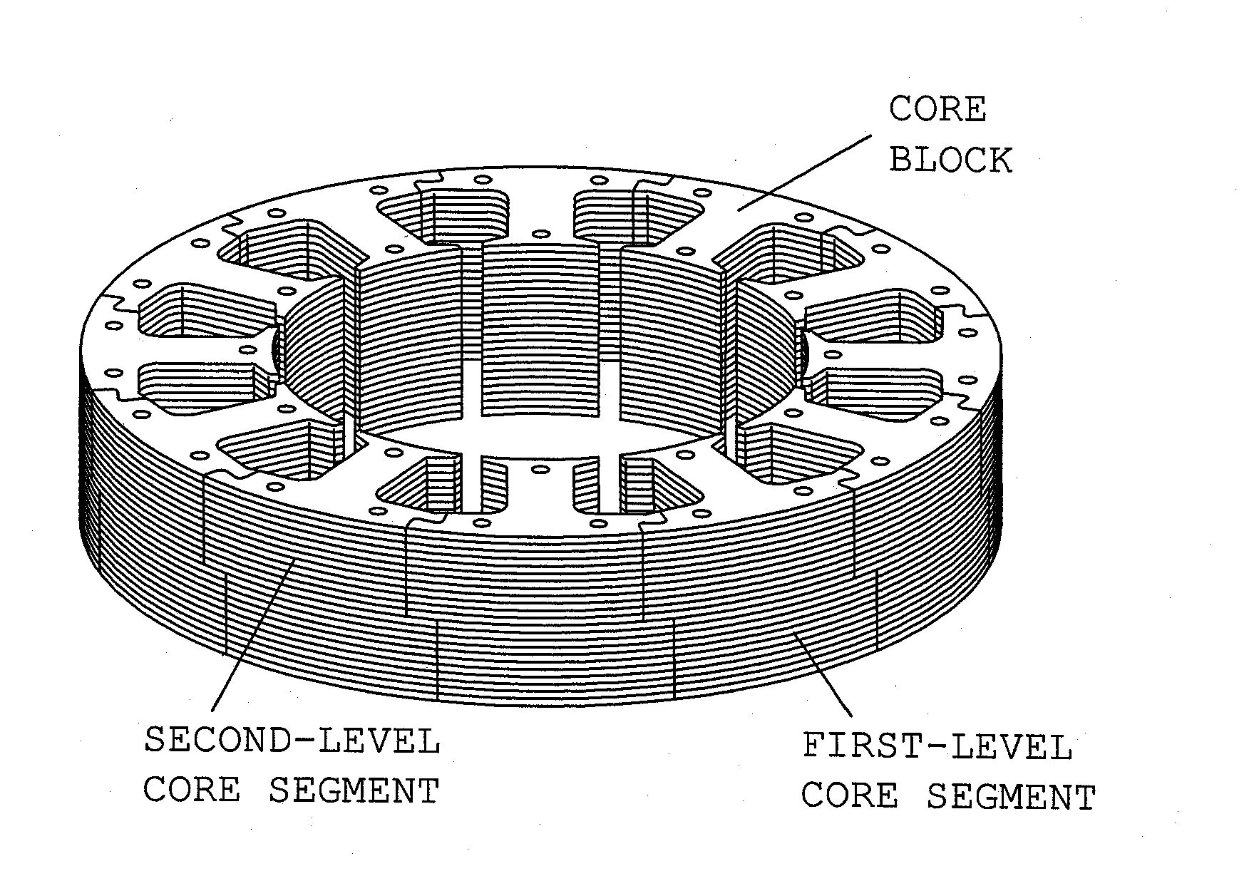
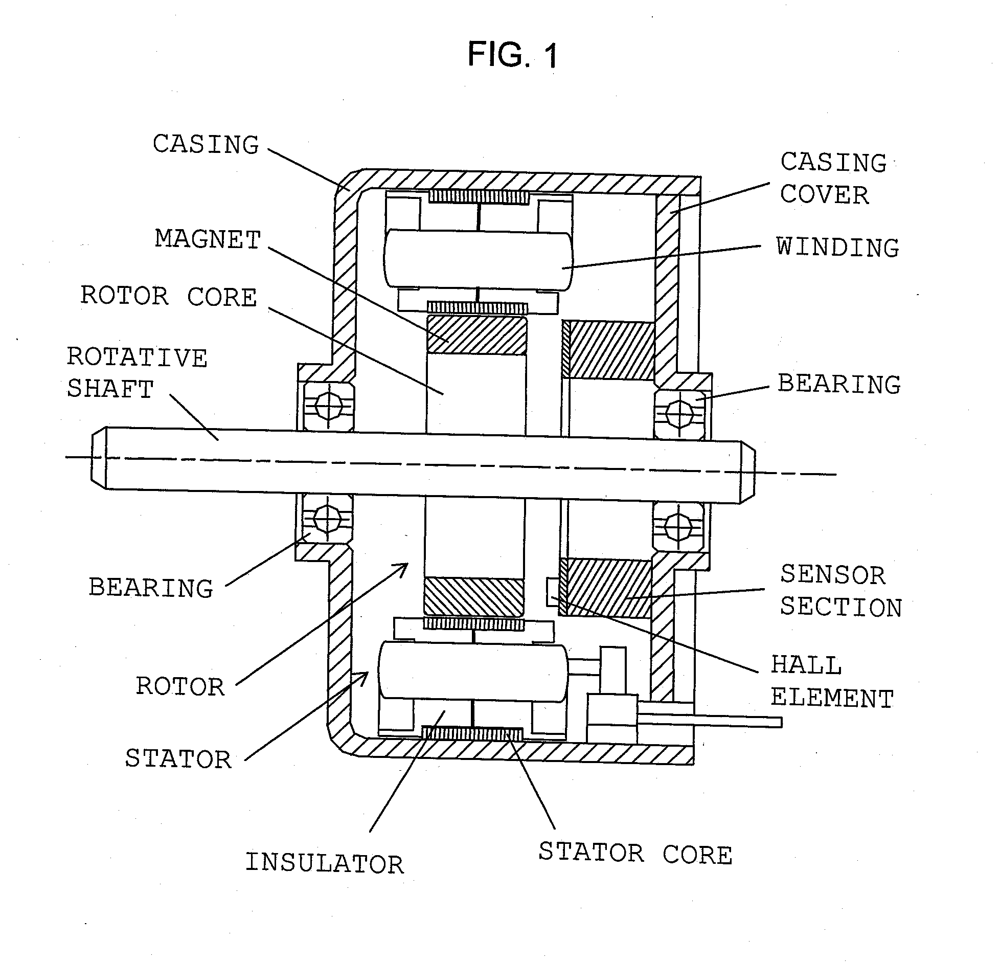
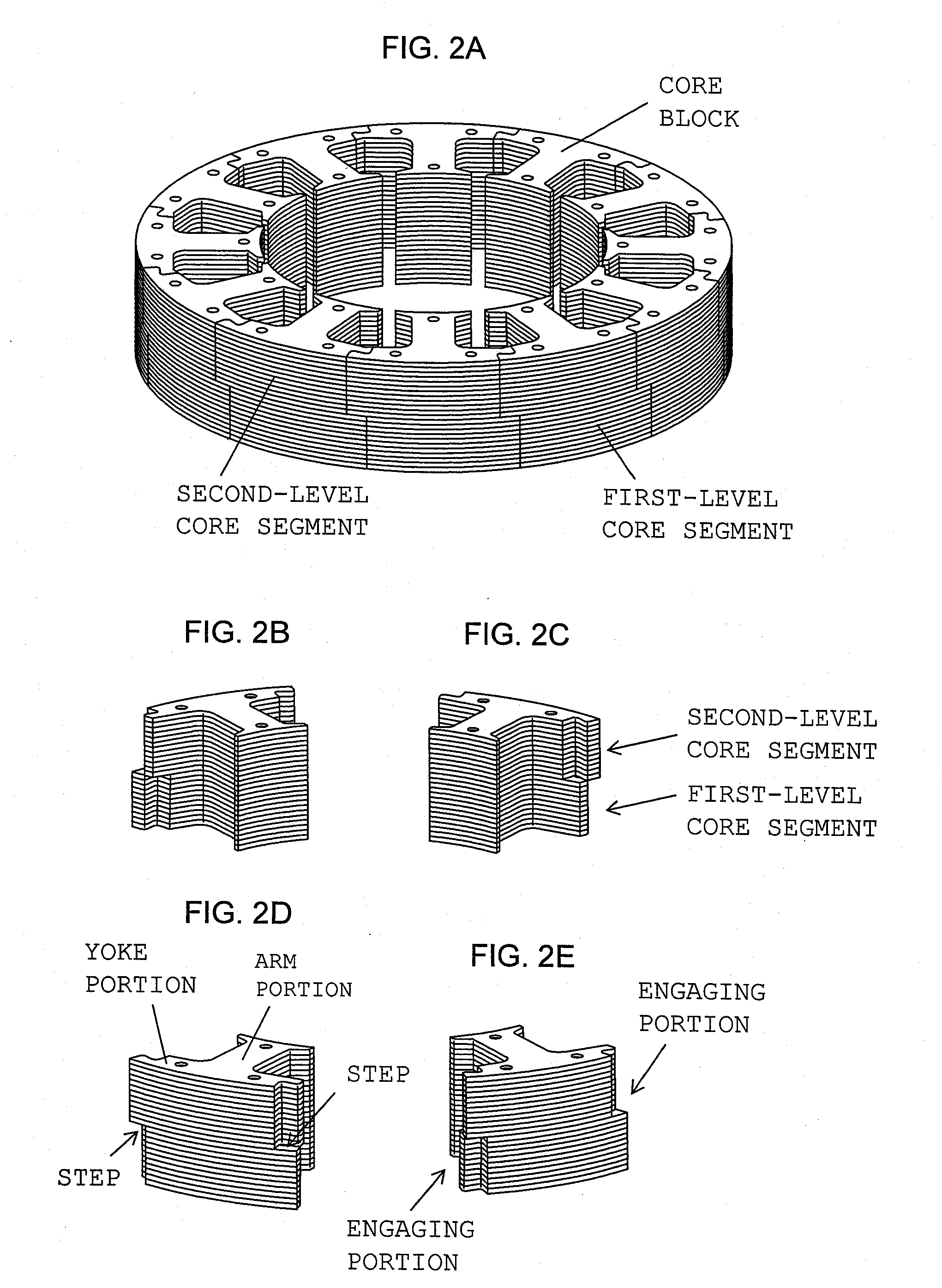
[0053]FIGS. 2A to 2E are views showing a stator core according to the present invention employed in the motor of FIG. 1. FIG. 2A is a perspective view showing an assembly of core blocks. FIGS. 2B to 2E are perspective views of a single core block as viewed from different directions. In actual practice, winding is performed on the individual core blocks which have undergone insulation treatment; then, the core blocks are fixedly joined together. However, for convenience of explanation, in FIG. 2 and the drawings appearing in the following description, the illustration of insulation treatment and winding is omitted. The insulation treatment and winding can be performed by use of known techniques.

[0054]The illustrated stator core is an assembly of 12 core blocks (12 poles) of the same shape. Each of the core blocks is configured such that core segments are stacked in two levels in the axial direction of the rotative shaft. A first-level core segment and a second-level core segment do n...

sixth embodiment

[0069]FIG. 11 is a perspective view of a single core block of a stator core according to the present invention. In the stator core, a single core block is configured such that three arm portions A to C are formed integral with a single arcuate yoke portion. In formation of, for example, the annular stator core (12 poles) shown in FIG. 2A, four core blocks (each having 3 poles) shown in FIG. 11 are connected. Engaging portions are provided at opposite ends of the yoke portion integrated with the three arm portions A to C. In the case where particular difficulty is not encountered in winding work as in winding of a thin wire, use of core blocks of the illustrated configuration is advantageous from the viewpoint of improvement of utilization of core material and a reduction in the number of man-hours required for engagement of core blocks. The present embodiment has been described while mentioning a core block configured such that three arm portions (3 poles) are integrated with a sing...

seventh embodiment

[0070]FIGS. 12A and 12B are views showing core blocks of different types of a stator core according to the present invention. FIGS. 12A and 12B are perspective views showing a core block of type A and a core block of type B, respectively. Both core blocks of type A and type B are symmetric. In the core block of type A, the second-level core segment has radially outer protrusions protruding from circumferentially opposite sides thereof, and the first-level core segment has radially inner protrusions protruding from circumferentially opposite sides thereof. The core block of type B is in reverse relation with that of type A; specifically, the first-level core segment has radially outer protrusions protruding from circumferentially opposite sides thereof, whereas the second-level core segment has radially inner protrusions protruding from circumferentially opposite sides thereof. Needless to say, the protrusions are accompanied by respective recesses. Similar to the above-described emb...


PUM


Abstract

A core block has an arm portion, and a yoke portion extending circumferentially at an end of the arm portion. At least the yoke portion is configured such that a plurality of core segments are stacked in multiple levels in an axial or radial direction. Each of the core blocks has engaging portions formed at respective opposite ends of the yoke portion and adapted to connect adjacent core blocks. In a first-level core segment, each of the engaging portions has a protrusion extending circumferentially from a corresponding one of the opposite ends of the yoke portion, and a recess juxtaposed radially to the protrusion and adapted to receive the protrusion of an adjacent core block. In a second-level core segment, each of the engaging portions has the protrusion and the recess provided in positionally reversed relation with those of the first-level core segment with respect to the radial direction.

Description

[0001]This application claims the benefit of Japanese Patent Application No. 2009-060910, filed Mar. 13, 2009 in Japan, the disclosures of which are incorporated herein by reference.BACKGROUND OF THE INVENTION [0002]1. Field of the Invention[0003]The present invention relates to a core block used in a number greater than one to configure a single annular magnetic pole core (yoke) through mutual connection of core blocks and to a magnetic pole core for a motor configured through annular integration of the core blocks.[0004]2. Description of the Related Art[0005]In, for example, an inner rotor brushless motor used to drive a motor-driven tool, a sensor for detecting position is attached to a stator and detects a magnetic pole of a magnet provided on a rotor, thereby performing switching control of current to be applied to the stator winding. The stator core of such a brushless motor is configured such that slots between magnetic poles for accommodating windings are opened radially inw...

Claims


Application Information

Patent Timeline
Patent Type & Authority Applications(United States)
IPC IPC(8): H02K1/18
CPCH02K1/24H02K1/148
Inventor KINOSHITA, NOBUO
Owner MABUCHI MOTOR
Why Eureka
Try Eureka