Wheel including a rim, a hub, and a device for connecting the rim to the hub

a technology of connecting device and wheel, which is applied in the field of wheels, can solve the problems of adding to the weight of the wheel, the overall weight of the vehicle to which the wheel is a part, and achieves the effects of reducing the inertia of the connecting device, facilitating manufacturing and assembling the device, and simple connection device structur

Inactive Publication Date: 2009-12-15
MAVIC SA
View PDF15 Cites 22 Cited by
  • Summary
  • Abstract
  • Description
  • Claims
  • Application Information

AI Technical Summary

Benefits of technology

[0022]A resulting advantage of the invention is that the inertia of the connecting device is reduced. Furthermore, the structure of the connecting device is simple, which makes manufacturing and assembling the device easier. Another advantage is that the fibers are biased in tension, along the longitudinal direction. This provides the spoke with greater strength. A further advantage results from the wheel being lighter; indeed, with a reduced inertia, the wheel provides an improved dynamic behavior. In the case of such a wheel used on a bicycle, for example, accelerating is easier.
is that the inertia of the connecting device is reduced. Furthermore, the structure of the connecting device is simple, which makes manufacturing and assembling the device easier. Another advantage is that the fibers are biased in tension, along the longitudinal direction. This provides the spoke with greater strength. A further advantage results from the wheel being lighter; indeed, with a reduced inertia, the wheel provides an improved dynamic behavior. In the case of such a wheel used on a bicycle, for example, accelerating is easier.

Problems solved by technology

However, metallic spokes have drawbacks, such as their heavy weight, which adds to the weight of the wheel and, of course, the overall weight of the vehicle to which the wheel is a part.
Another drawback of metallic spokes is their relatively low resistance to tension forces or material fatigue, which requires that the tension in each spoke be monitored during assembly and use.
For example, the arrangement by which the spoke is connected to the rim or to the hub is heavy and complicated.
The combination of the shank and the clevis forms a bulky and heavy articulation.
Furthermore, its implementation is complicated because some provision is required to be made for connecting the clevis to the rim or to the hub.
As a consequence, the benefits gained in a reduction in the weight of the body of the spoke are lost, at least in part, by the disadvantage in the increase in the weight of the connection.
However, the connection assembly with which it is associated remains relatively bulky and heavy because they enclose the loops.
Furthermore, manufacturing and implementing the connection assembly are relatively complicated.
Furthermore, the connection assembly for FR 2 792 251 is relatively complex.

Method used


Image

  • Wheel including a rim, a hub, and a device for connecting the rim to the hub
  • Wheel including a rim, a hub, and a device for connecting the rim to the hub
  • Wheel including a rim, a hub, and a device for connecting the rim to the hub

Examples


first embodiment

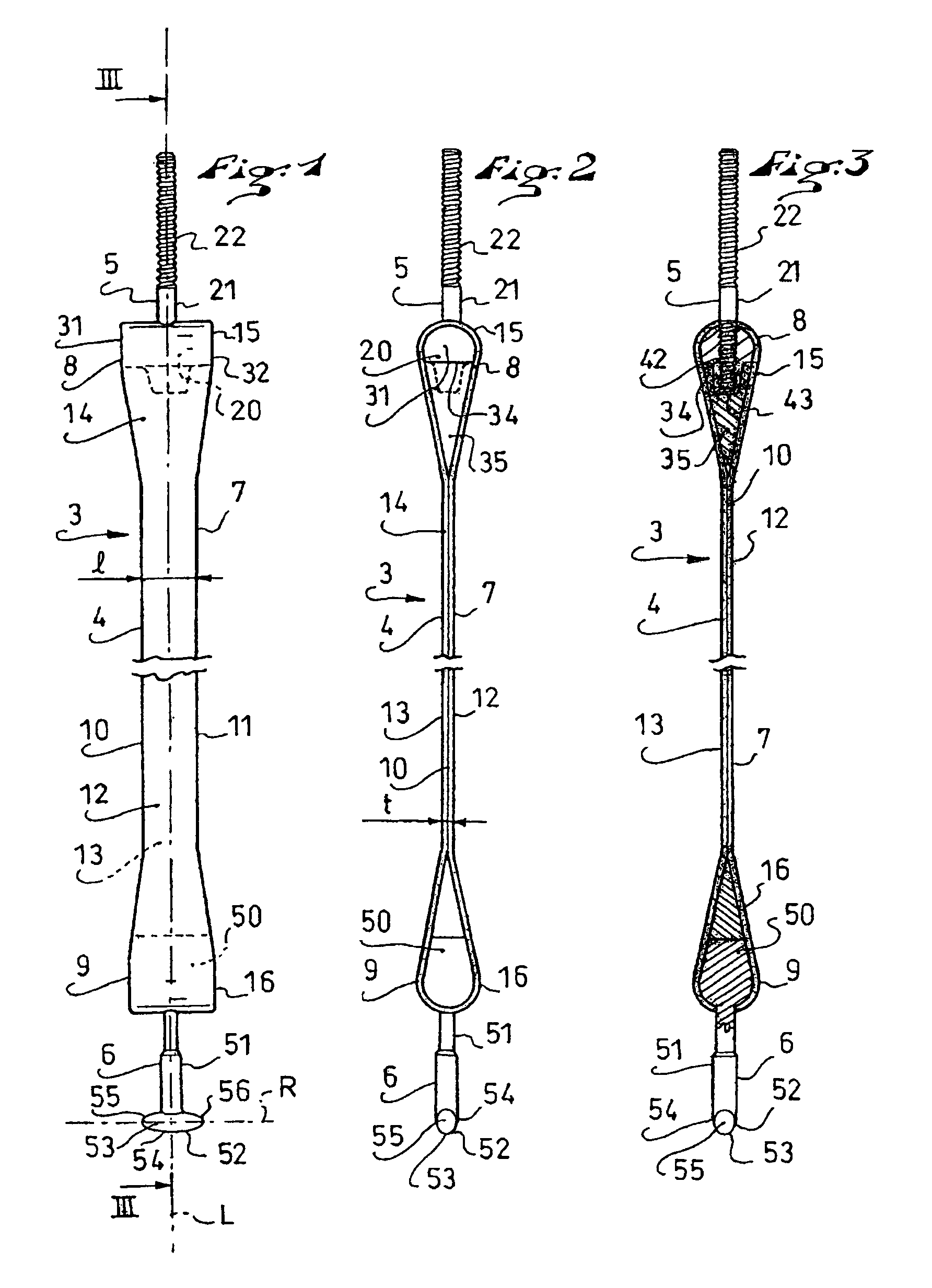
[0041]the invention is shown in FIGS. 1 to 8.

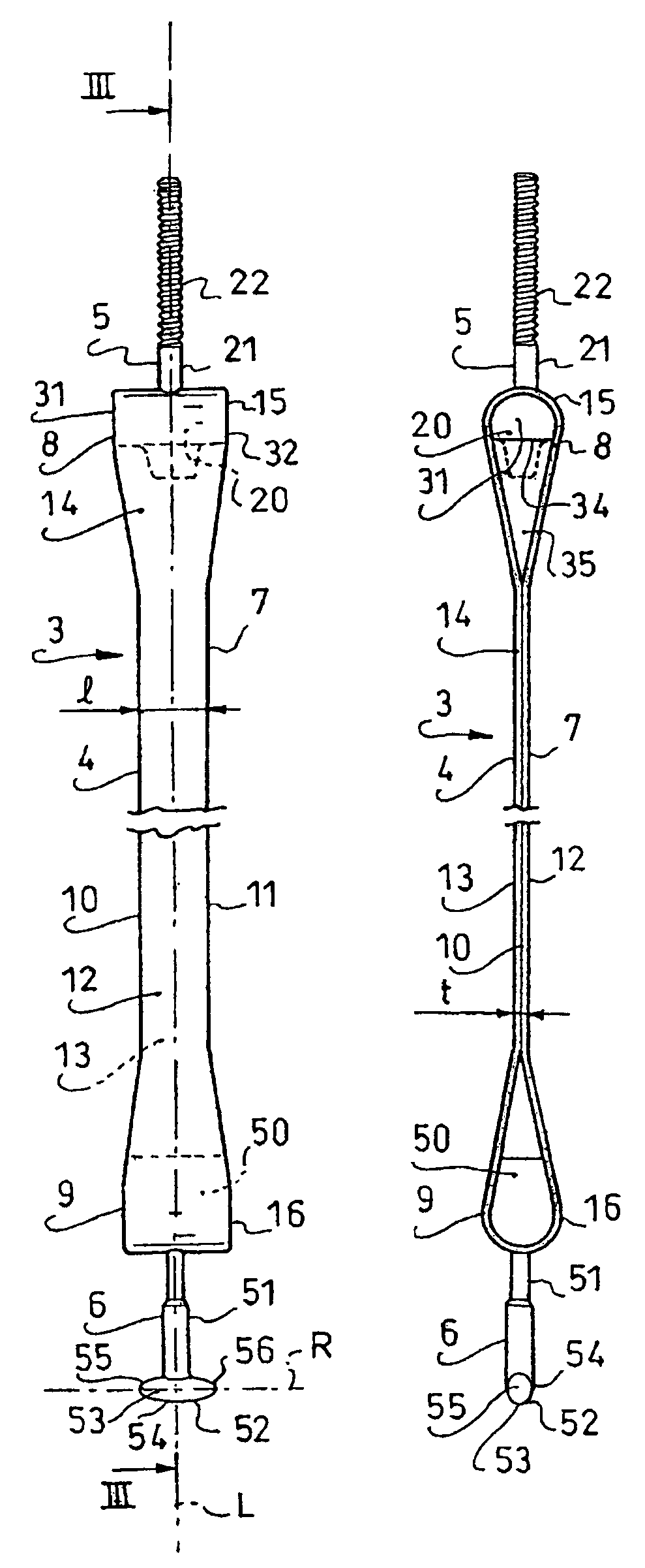
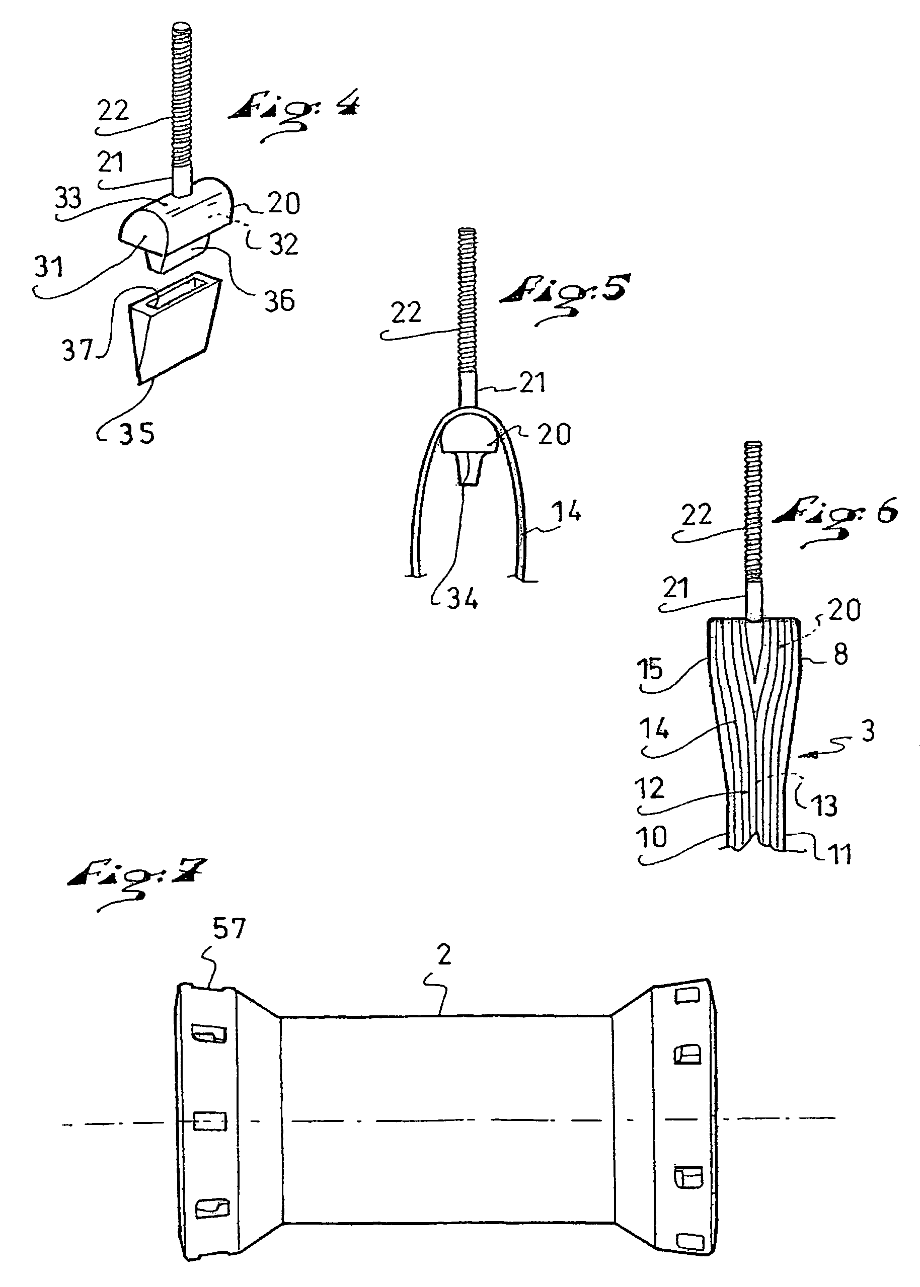
[0042]As can be understood from FIGS. 1, 2, 3, and 8, a wheel includes a rim 1, a hub 2, and at least one device 3 for connecting the rim 1 to the hub 2.

[0043]The connecting device 3 includes a composite spoke 4, a first mechanism 5 for connecting the spoke 4 to the rim 1, as well as a second mechanism 6 for connecting the spoke 4 to the hub 2.

[0044]The composite spoke 4 itself includes an elongated body 7, which extends along a longitudinal direction L between a first end 8 and a second end 9. The elongated body 7 extends width-wise between a first side 10 and a second side 11, and thickness-wise between a first surface 12 and a second surface 13.

[0045]The elongated body 7 and the ends 8, 9 include fibers 14.

[0046]According to the first embodiment of the invention that is illustrated, the fibers 14 are arranged to form a first loop 15 at the first end 8, as well as a second loop 16 at the second end 9. Thereby, the first end 8 includes t...

second embodiment

[0070]The second embodiment is shown in FIG. 9. A connecting device includes a composite spoke 65 as well as a connecting mechanism provided with a shank 66. The shank 66 is screwed into an insert 67 after the spoke 65 has been shaped by means of the mold. To this end, the spoke 65 is pierced with a drill, for example, in the area of a loop 68. Thereby, the spoke 65 can maintain a constant width over its entire length, that is, in the area of the body and ends. Local reinforcements can be added in order to compensate for a structural weakening due to piercing.

third embodiment

[0071]the invention is shown in FIG. 10. A connecting device includes a composite spoke 75, as well as a connecting mechanism provided with a shank 76 and an insert 77. Here, the spoke 75 includes two distinct arms 78, 79 separated by a clearance 80. The width of the clearance is, for example, close to or equal to that of the shank 76. The two arms 78, 79 have the same width, for example. The clearance extends from the shank 76. Thus, the forces are balanced. A resulting advantage of this construction is an even lighter spoke 75.


PUM


Abstract

A wheel including a rim, a hub, and at least one device for connecting the rim to the hub, the connecting device including a composite spoke and a first mechanism to connect the spoke to the rim or the hub, the spoke including an elongated body, which extends in a longitudinal direction, between a first end and a second end, the body and the ends including fibers, the fibers being arranged to form a first loop at the first end. The first connecting mechanism includes a first insert housed in the first loop, a first shank affixed to the first insert, the first shank being oriented along the longitudinal direction, a first screw or fastening portion being defined on the first shank.

Description

CROSS-REFERENCE TO RELATED APPLICATIONS[0001]This application claims priority under 35 U.S.C. § 119 of French Patent Application No. 05.13086, filed on Dec. 21, 2005, and French Patent Application No. 06.02877, filed on Apr. 3, 2006, the disclosures of which are hereby incorporated by reference thereto in their entireties.BACKGROUND OF THE INVENTION[0002]1. Field of the Invention[0003]The invention relates to the field of wheels, each of which includes a rim, a hub, and at least one device for connecting the rim to the hub, with the connecting device including at least one composite spoke and one mechanism for connecting the spoke to the rim or to the hub. The invention also relates to the connecting device itself.[0004]More particularly, the invention relates to wheels and connecting devices of the aforementioned type, which are adapted to bicycles, as well as to other vehicles such as wheelchairs, or the like.[0005]2. Description of Background and Relevant Information[0006]A devic...

Claims


Application Information

Patent Timeline
Patent Type & Authority Patents(United States)
IPC IPC(8): B60B5/00B60B1/02
CPCB60B1/003B60B1/006B60B1/0261B60B1/0284B60B21/062B60B1/042B60B1/044B60B5/02B60B21/025B60B1/041
Inventor MERCAT, JEAN-PIERRERENARD, PHILIPPE
Owner MAVIC SA
Why Eureka
Try Eureka