Optical disc apparatus for recording and/or reproducing information on/from an information surface of a rotatable optical disc

a technology of optical discs and information surfaces, which is applied in the direction of data recording, disposition/mounting of heads, instruments, etc., can solve the problems of undue vibration and distortion, force moments exerted, and added load of swing arm spindles, so as to reduce the overall dimension of optical disc apparatus, reduce the inertia thereof, and minimize space requirements

Inactive Publication Date: 2006-11-14
KONINKLIJKE PHILIPS ELECTRONICS NV
View PDF6 Cites 1 Cited by
  • Summary
  • Abstract
  • Description
  • Claims
  • Application Information

AI Technical Summary

Benefits of technology

[0017]In an optical disc apparatus of the kind in which the invention may be advantageously applied, much of the optical lens unit associated with the supporting assembly, such as the laser source and the associated optical and electronic means necessary to send data to and/or receive data from the information disc, will be located near the swing axis of the swing arm assembly so as to reduce the inertia thereof. The laser beam will travel along a section of the light path between the focussing lens assembly and the laser source which intersects the focussing axis of the focussing lens assembly perpendicularly. In an advantageous embodiment of the invention of the kind in which the laser beam intersects the focussing axis perpendicularly, the optical lens assembly comprises, near the free end of the arm assembly, a perpendicularly reflecting optical element connected to the focussing lens, having a reflective surface on the side of the focussing lens which is directed away from the information surface of a mounted optical disc and causes reflection of a laser beam travelling in the general direction between the swing axis and the focussing axis so as to travel through the focussing lens generally along the focussing axis, and the movable magnetic focussing means is connected to the reflecting element in a position in the side of the reflecting surface which is directed away from the movable focussing lens. The magnetic focussing means can thus be positioned on the focussing axis of the focussing lens.
[0018]The previous embodiment may be advantageously combined with a further embodiment of the invention, wherein the swing arm assembly is bounded by spaced virtual parallel flat planes extending perpendicularly to the swing axis, a first plane being nearer to a mounted optical disc and a second plane being more remote from a mounted optical disc; at least a portion of the reflecting element is inwardly spaced from the second plane, so that an intermediate space is provided between the reflecting element and the s...

Problems solved by technology

Moreover, these forces act on the focussing lens assembly and, therefore, on the swing arm assembly at some distance from the focussing axis of the focussing lens, resulting in force moments exerted on the resilient arm elements of the swing arm assembly.
Thus, eccentric forces and moments are dynamically produced during the focussing of the focussing lens; this will produce dynamic reaction forces and moments in ...

Method used


Image

  • Optical disc apparatus for recording and/or reproducing information on/from an information surface of a rotatable optical disc
  • Optical disc apparatus for recording and/or reproducing information on/from an information surface of a rotatable optical disc
  • Optical disc apparatus for recording and/or reproducing information on/from an information surface of a rotatable optical disc

Examples


Embodiment Construction

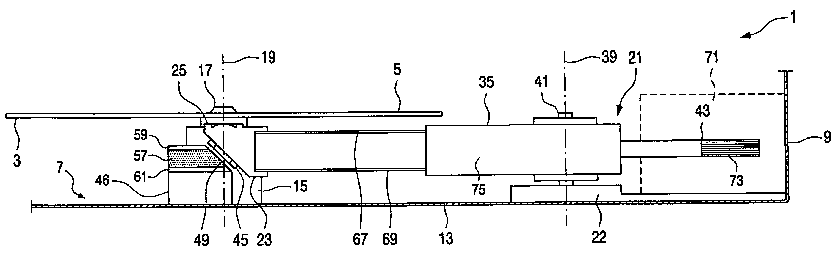
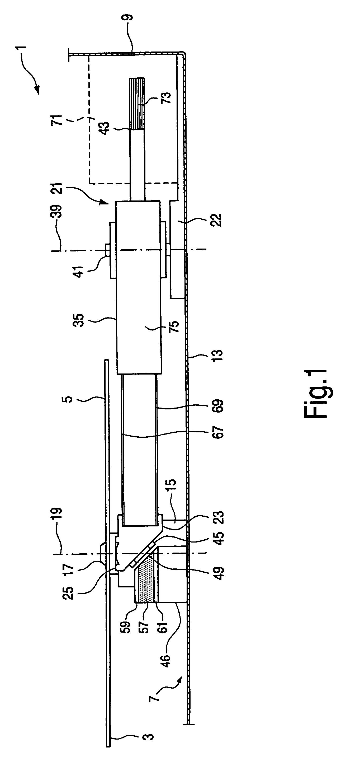
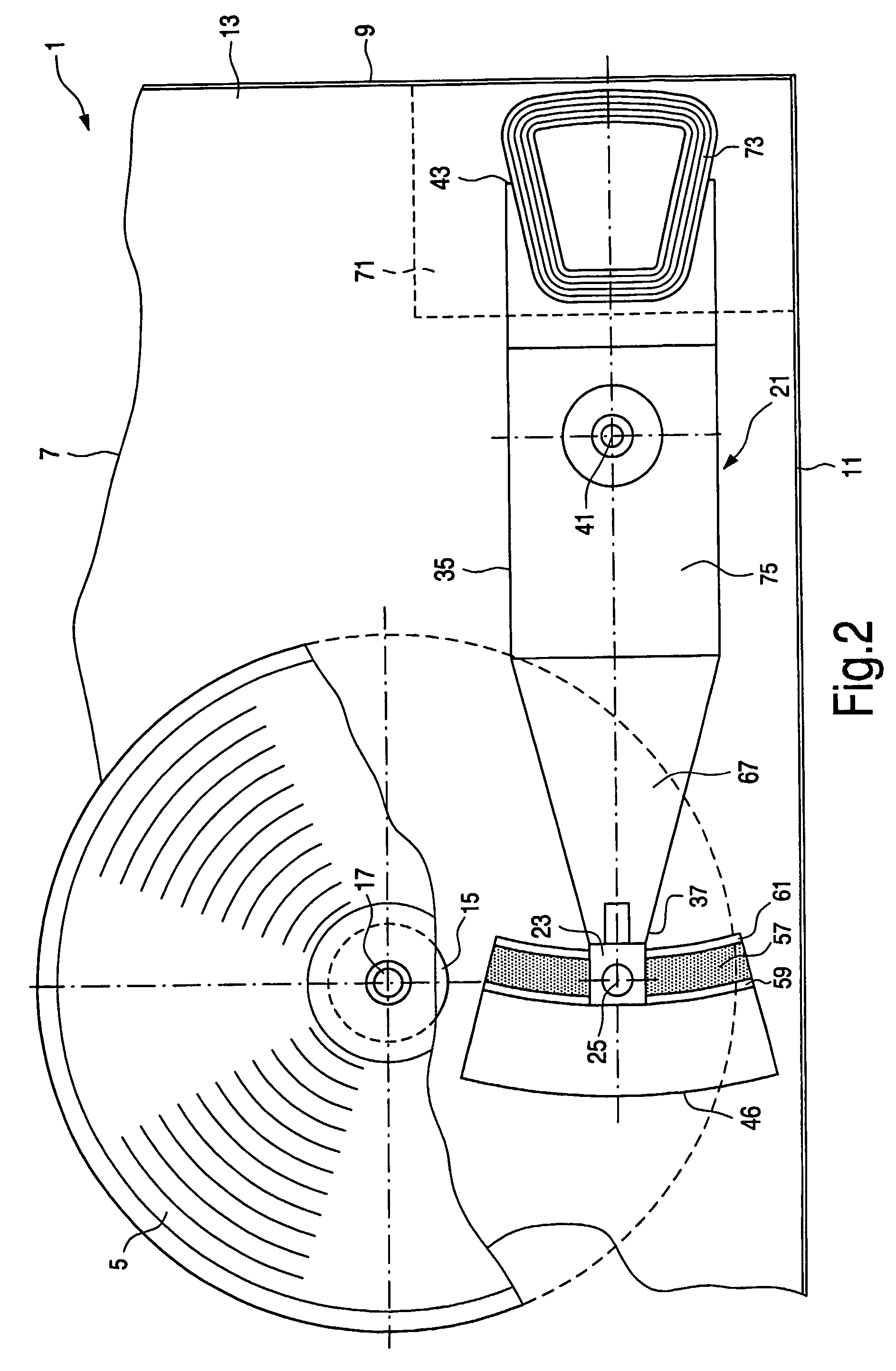
[0026]FIGS. 1 and 2 show an overall configuration of an optical disc apparatus 1 for recording and / or reproducing information on / from an information surface 3 of a rotatable optical disc 5. The apparatus comprises a supporting assembly 7 with side walls 9, 11 and a bottom wall 13. The supporting assembly is only partly shown and may be of an arbitrary configuration, but in many cases it will be generally box shaped. A spindle motor 15 is provided on the bottom wall 13 of the supporting assembly 7; this motor has a spindle 17 with a spindle axis 19 for rotating the optical disc 5 about the spindle axis 19. The optical disc may be mounted on or put on and / or clamped to the spindle.

[0027]An optical lens unit 21 is provided on a raised part 22 provided on the bottom surface 13 of the supporting assembly 7 in order to scan the information surface 3 on the bottom side of the optical disc 5 mounted on the spindle 17. The optical lens unit 21 comprises a movable focussing lens assembl...


PUM


Abstract

An optical disc apparatus (1) for recording and/or reproducing information on/from an information surface (3) of a rotatable optical disc (5), includes a supporting assembly (7), a spindle motor (15), associated with the supporting assembly (7), having a spindle (17) with a spindle axis (19) for rotating the optical disc (5), an optical lens unit (21) associated with the supporting assembly (7) for scanning an information surface (3) of said optical disc (5) mounted on the spindle (17), and including a focussing lens assembly (23) having a focussing lens (29), a swing arm assembly (35) which is rotatable about a swing axis (39), having a movable magnetic focussing unit (45) provided near a free end (37) of the swing arm assembly (35), for driving the the movable focussing lens assembly, and consequently, the focussing lens (29) along the focussing axis (31) so as to focus the optical beam (33) on the optical disc information surface (3), and a stationary magnetic focussing unit (46) magnetically cooperating through an intermediate air gap (48) with the movable magnetic focussing unit (45). The stationary and movable magnetic focussing units (46, 45) are disposed and cooperate such that the force vector component (P) intersects a focussing lens area (27) bounded by a focussing lens periphery.

Description

BACKGROUND OF THE INVENTION[0001]1. Field of the Invention[0002]The present invention relates to an optical disc apparatus for recording and / or reproducing information on / from an information surface of a rotatable optical disc.[0003]2. Description of the Related Art[0004]An optical disc apparatus of the kind indicated above is known from U.S. Pat. No. 6,052,357. This patent describes an optical disc apparatus for recording and / or reproducing information on / from an information surface of a rotatable optical disc, comprising a supporting assembly and a spindle motor, associated with the supporting assembly, having a spindle with a spindle axis for rotating the optical disc, mounted on the spindle, about the spindle axis. An optical lens unit is associated with the supporting assembly in order to scan an information surface of the optical disc mounted on the spindle. The optical lens unit comprises a focussing lens assembly having a movable focussing lens having a focussing lens area b...

Claims


Application Information

Patent Timeline
IPC IPC(8): G11B7/085G11B7/09
CPCG11B7/08576G11B7/0927G11B7/085G11B7/08G11B7/09
Inventor ROSMALEN, GERARD EDUARD
Owner KONINKLIJKE PHILIPS ELECTRONICS NV
Why Eureka
Try Eureka